Flow Rate Regulation Valve

a flow rate regulation and valve body technology, applied in the direction of engine components, pipe elements, mechanical equipment, etc., can solve the problems of adversely affecting the yield of the semiconductor device to be manufactured, and the inability to obtain a comparatively compact flow rate regulation valv

Inactive Publication Date: 2008-05-15
SURPASS IND
View PDF8 Cites 35 Cited by
  • Summary
  • Abstract
  • Description
  • Claims
  • Application Information

AI Technical Summary

Benefits of technology

[0011]The flow rate after opening the valve would increase exponentially only if the first valve body is provided so as to abut with the valve seat, while the flow rate after slowly opening the valve would increase only if the second valve body is inserted in the valve hole. In contrast in the first aspect of the invention, the provision of both the first valve body that abuts with the valve seat and the second valve body to be inserted in the valve hole mixes the aforementioned two features in the small flow rate area and flow rate increases substantially linear immediately after opening the valve. The flow rate of the fluid, once increased to a certain level, increases substantially linear in a more stable fashion. Specifically, in the first aspect, the fluid can be supplied in a stable fashion with the flow rate maintaining linear from a closed state to the fully open state.
[0014]Specifically, in the second and third aspects, the first and second valve bodies are such a shape that the flow rate is comparatively smooth from the small flow rate area to the large flow rate area and the difference in the flow rate that changes between the small and large flow rate areas is eliminated. In this way, flow rate is easily regulated by obtaining a flow rate that is linear over the entire range and fluid can be supplied in a stable fashion over the entire range. Incidentally, the first and second valve bodies are preferably in the shape of a truncated cone.
[0016]Specifically, in the fourth aspect, the fluid can be supplied in a stable fashion with a flow rate that is linearly maintained even for a diaphragm-type needle valve.
[0017]All the aspects described above share the advantage that fluid can be supplied in a stable fashion with a flow rate that is linearly maintained from a closed state to a fully open state.
[0018]Further, the second and third aspects have an advantage in that the difference in flow rate is eliminated in the boundary between the small and large flow rate areas, and fluid can be supplied in a stable fashion with a flow rate that is linearly maintained.
[0019]Furthermore, the fourth aspect has an advantage in that fluid can be supplied in a stable fashion with a flow rate that is linearly maintained even for a diaphragm-type needle valve.

Problems solved by technology

In such a case, the flow rate regulation valve itself increases in size, and therefore, it is impossible to obtain a comparatively compact flow rate regulation valve.
In such a case, the instability of the flow rate of a chemical liquid, such as the etching solution or developer adjusted by the flow rate regulation valves 100, 100′ has adversely effected the yield of the semiconductor device to be fabricated.

Method used


Image

  • Flow Rate Regulation Valve
  • Flow Rate Regulation Valve
  • Flow Rate Regulation Valve

Examples


Embodiment Construction

[0031]The embodiments of the invention are described below with reference to the accompanying drawings. In the drawings, similar component members are designated by the same reference numerals, respectively. To facilitate understanding, the scale of these drawings has been appropriately changed.

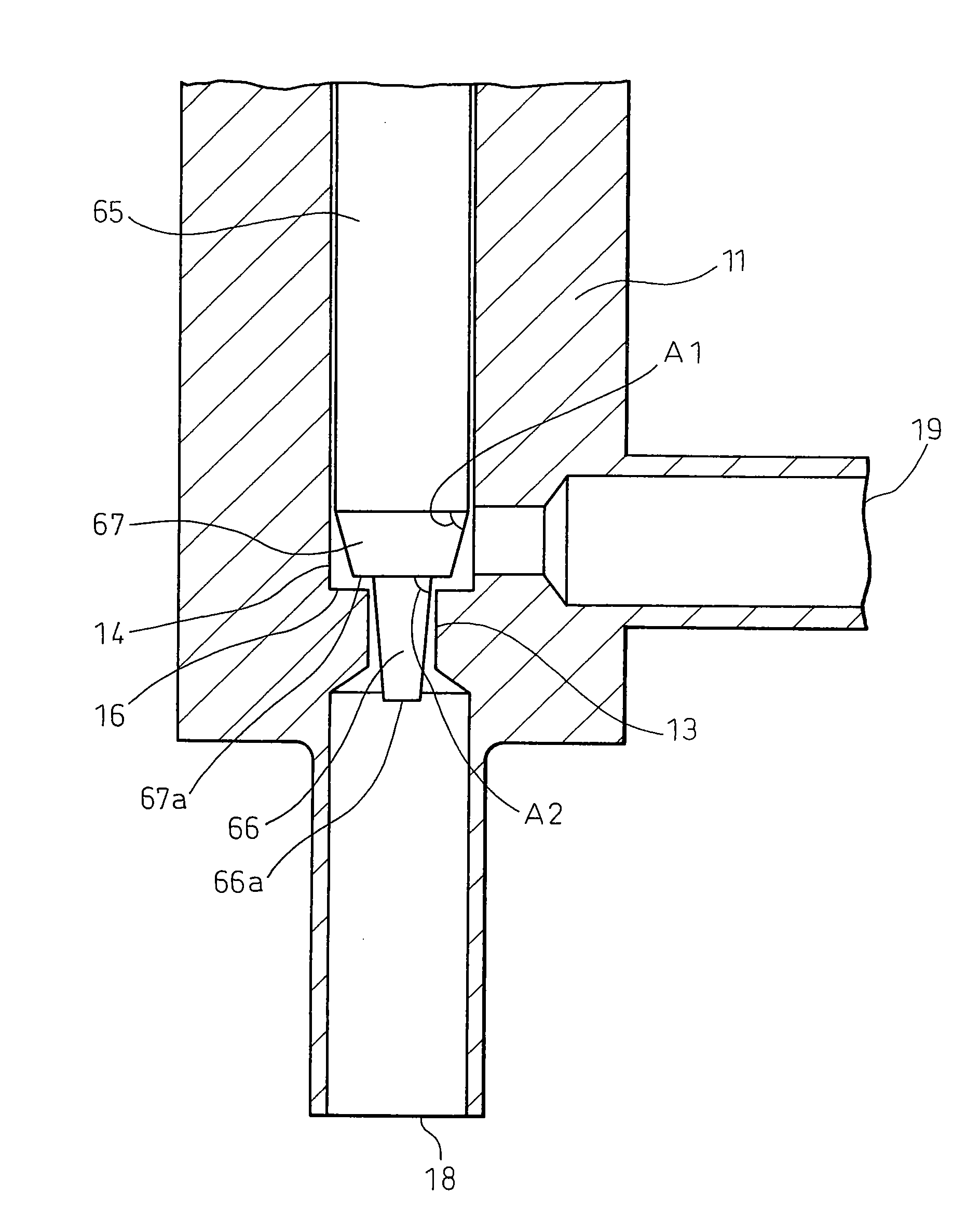
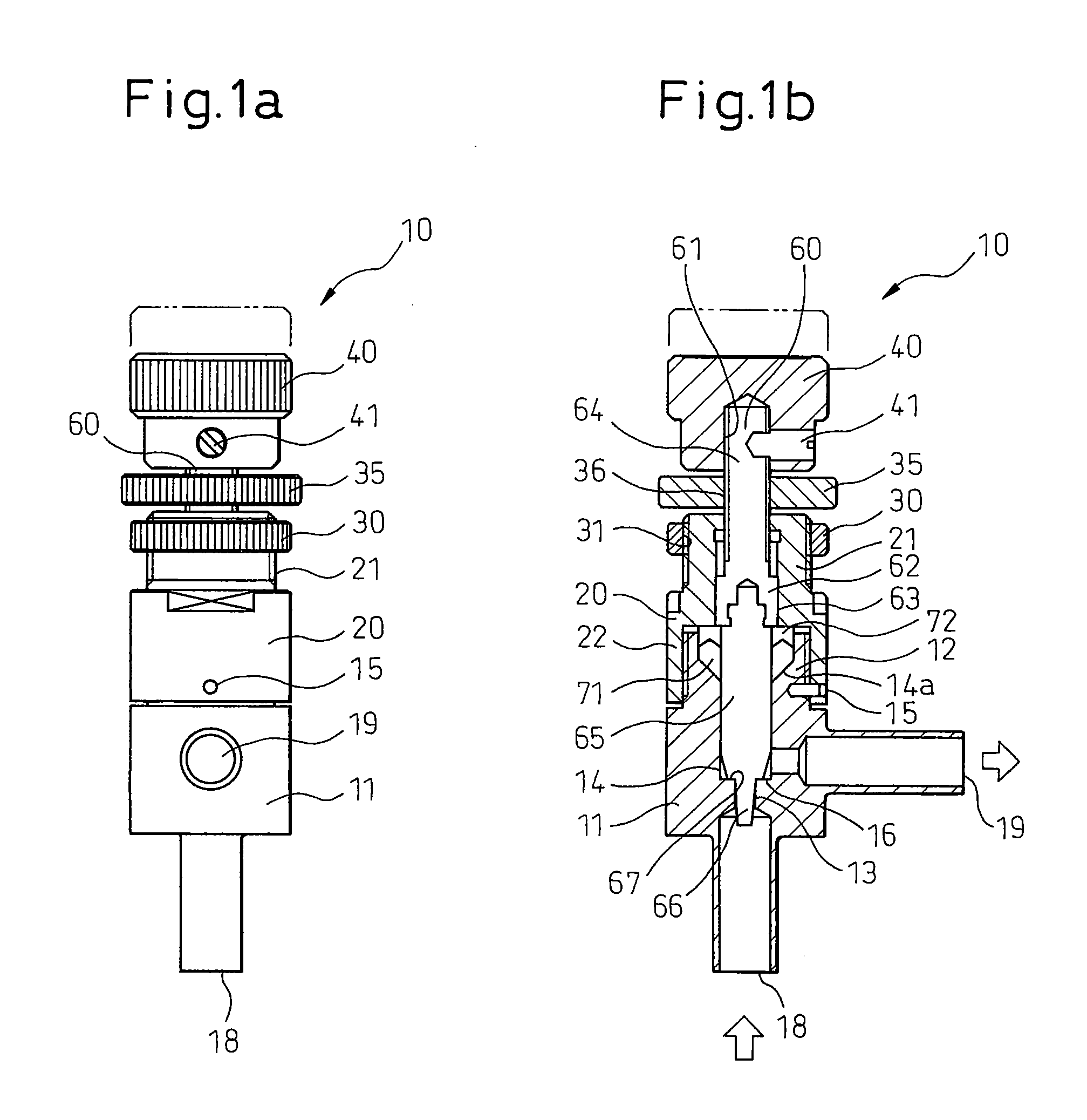
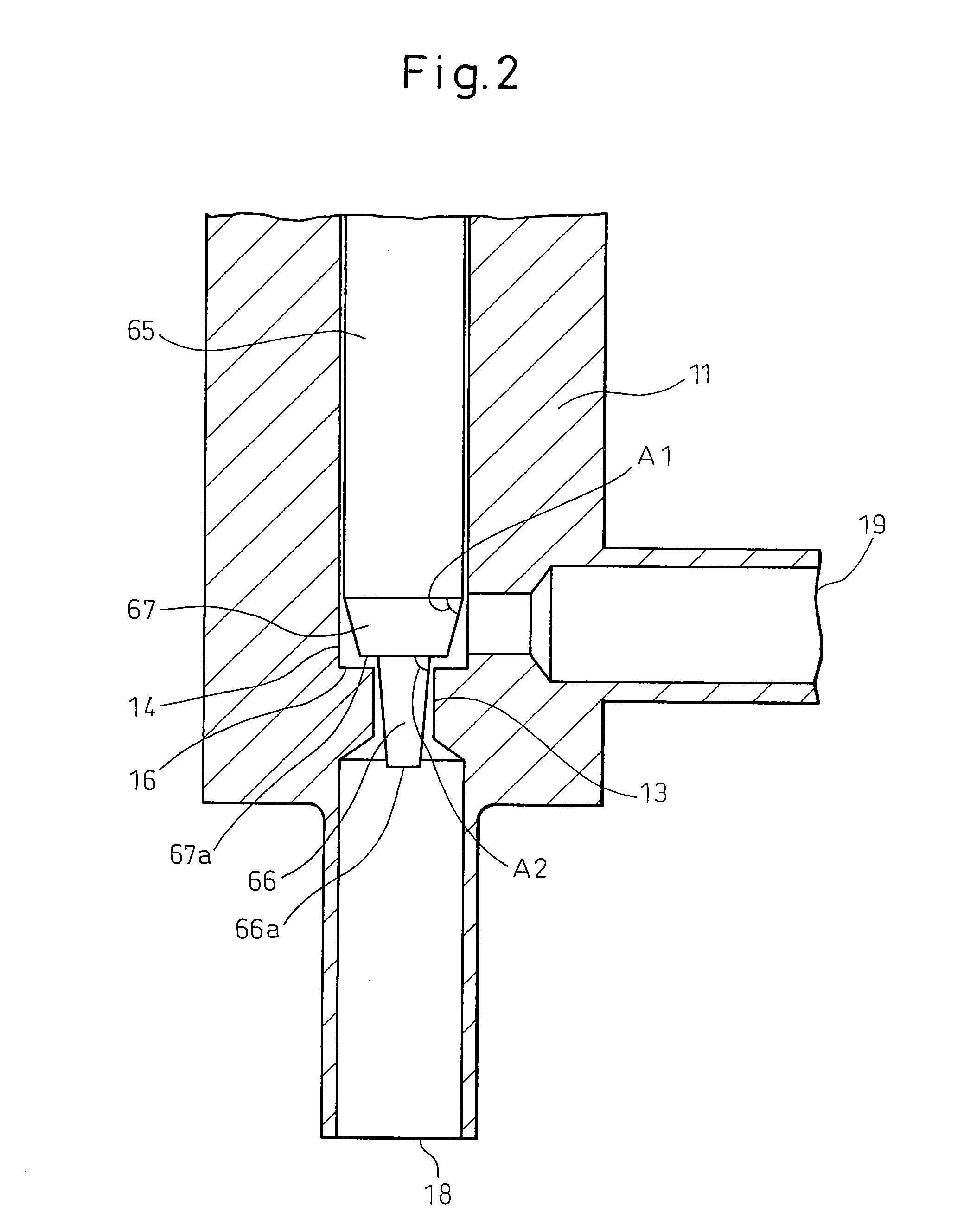
[0032]FIG. 1a is a front view of a flow rate regulation valve according to an embodiment of the invention, and FIG. 1b a side sectional view of the flow rate regulation valve according to an embodiment of the invention. As shown in these drawings, the housing of the flow rate regulation valve 10 according to the invention is configured of a lower portion 11 and an upper portion 20. The lower portion 11 of the housing is formed with an inlet 18 and an outlet 19. The inlet 18 and the outlet 19 communicate with each other in the lower portion 11 through a valve hole 13 and an axial hole 14 described later.

[0033]As can be seen from FIG. 1b, a lower sleeve 12 that is narrower than the lower portio...


PUM


Abstract

A flow rate regulation valve (10) comprises a housing (11) formed with an axial hole (14) and a valve hole (13) communicating with the axial hole, a needle valve (60) adapted to move within the axial hole relative to a valve seat located between the axial hole and the valve hole, and a flow rate adjust knob (40) mounted at the proximal end of the needle valve extending from the housing. The needle valve is moved relative to the valve seat by rotating the flow rate adjust knob thereby to regulate the flow rate of the fluid flowing through the valve hole. A first valve body (67) is arranged at the forward end of the needle valve and a second valve body (65) extends from the end surface (67a) of the first valve body. The cross section of the first valve body is larger than that of the second valve body, so that at the time of closing the flow rate regulation valve, the end surface of the first valve body abuts with a valve seat (16) located between the axial hole and the valve hole, and the second valve body is inserted in the valve hole. As a result, fluid can be supplied in a stable fashion with a flow rate that is linearly maintained.

Description

TECHNICAL FIELD[0001]This invention relates to a flow rate regulation valve for regulating flow rate by moving a needle valve relative to a valve seat.BACKGROUND ART[0002]A flow rate regulation valve is now used in various fields. FIG. 6a is a partially enlarged view of a flow rate regulation valve similar to the one disclosed in the prior art, for example, Japanese Unexamined Patent Publication No. 11-230407. As shown in FIG. 6a, the housing 110 of this flow rate regulation valve 100 is formed with an inlet 180 and an outlet 190 communicating with each other through a valve hole 130 and an axial hole 140. As shown, the valve hole 130 is narrower than the axial hole 140. A needle valve 600 is inserted in the axial hole 140, and a substantially conical valve body 650 is arranged at the forward end of the needle valve 600. As shown, the proximal end of the valve body 650 and the forward end of the needle valve 600 coincide with each other. In this flow rate regulation valve 100, the f...

Claims


Application Information

Patent Timeline
Patent Type & Authority Applications(United States)
IPC IPC(8): F16K47/00
CPCF16K1/06F16K1/54F16K1/38
Inventor HASUNUMA, MASAHIRO
Owner SURPASS IND
Why Eureka
Try Eureka