Recording-head driving device for driving recording head

a driving device and recording head technology, applied in printing and other directions, can solve the problems of cumbersome connection of wiring boards to body-side control devices, increased heat generation of actuator sections, and negative effects of actuator sections, so as to reduce the heat generation of drive-circuit units, reduce the number of wires, and simplify the layout of plurality of wires

Inactive Publication Date: 2008-05-15
BROTHER KOGYO KK
View PDF1 Cites 16 Cited by
  • Summary
  • Abstract
  • Description
  • Claims
  • Application Information

AI Technical Summary

Benefits of technology

[0010]In this recording-head driving device according to the present invention, the two drive-circuit units are provided, whereby the number of the plurality of wires connected to each of the two drive-circuit units can be decreased, a load imposed on each of the two drive-circuit units can be reduced and a layout of the plurality of wires can be simplified. Further, although each of the two drive-circuit units is a source of heat generation, an influence of the heat generation is not increased even if the two drive-circuit units are provided because the two drive-circuit units are away or distant from each other, with the plurality of actuator sections being interposed therebetween. Further, since the two drive-circuit units are disposed such that an area w

Problems solved by technology

Further, it is cumbersome to connect the wiring boards to a body-side control device.
If the two recording heads are provided by a single piece unit with the two drive-circuit units which are disposed on a single wiring board that

Method used


Image

  • Recording-head driving device for driving recording head
  • Recording-head driving device for driving recording head
  • Recording-head driving device for driving recording head

Examples


Embodiment Construction

[0018]Hereinafter, there will be described a preferred embodiment of the present invention by reference to the drawings. It is noted that, in this embodiment, there is adopted an inkjet recording head for color recording.

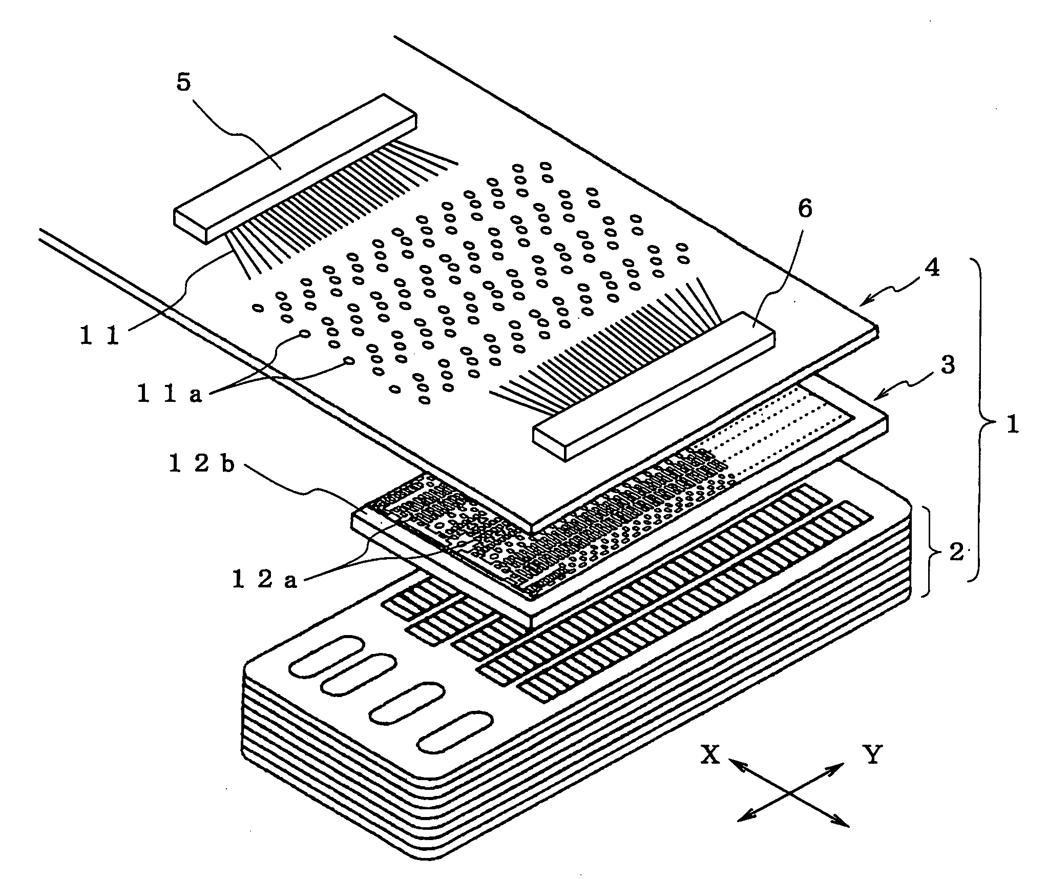
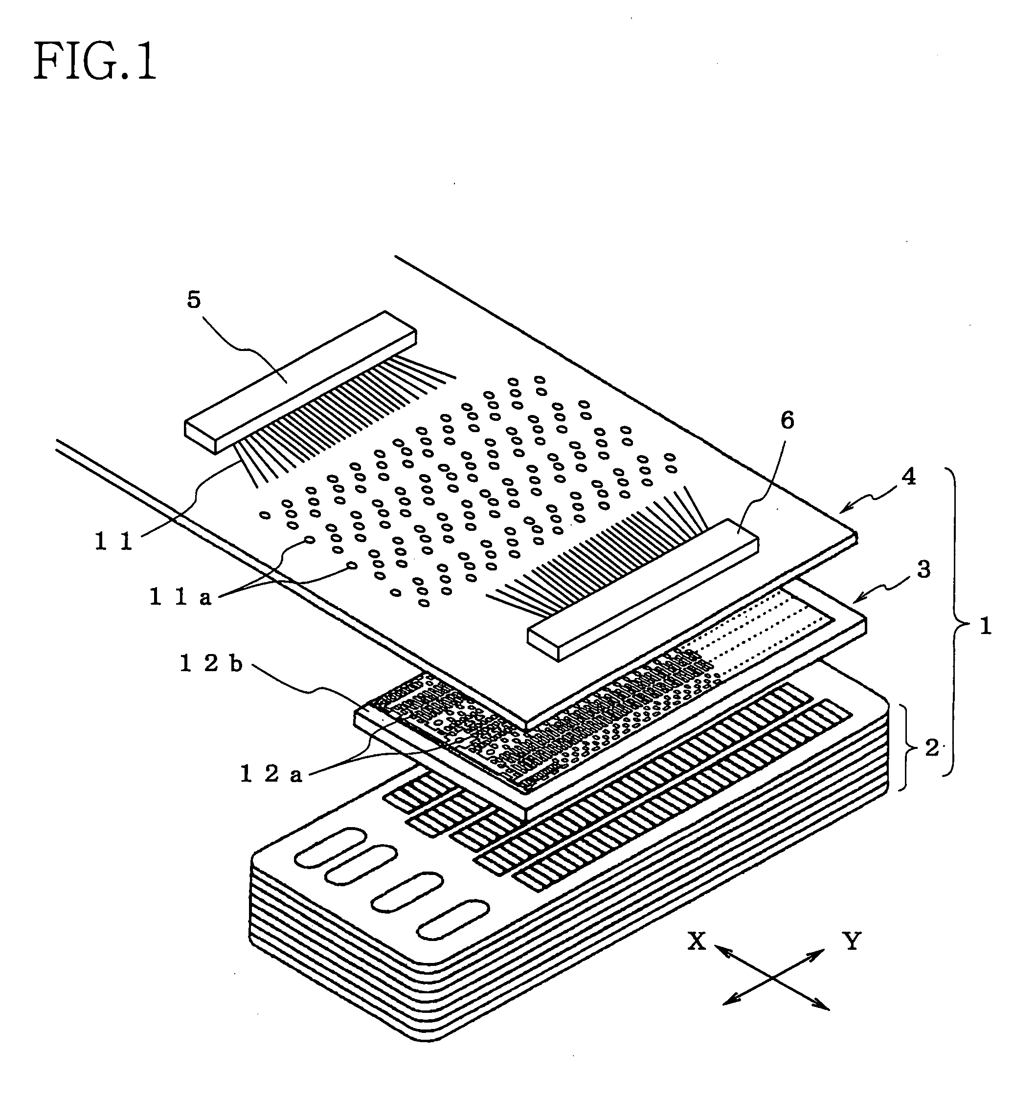
[0019]FIG. 1 is a perspective view showing a situation in which a flexible wiring board is superposed on and bonded to an upper surface of the recording head, according to the present invention.

[0020]As shown in FIG. 1, a recording head 1 includes an ink-channel unit 2 and an actuator unit 3 which are superposed on the ink-channel unit 2. The ink-channel unit 2 includes a plurality of nozzles each opening in a lower surface of the ink-channel unit 2 and a plurality of ink channels respectively corresponding the plurality of nozzles. The actuator unit 3 includes a plurality of actuator sections (not shown) each corresponds to one of the ink channels. As generally known, a piezoelectric element or a heater for boiling an ink can be adopted as each of the actuator sect...


PUM


Abstract

A recording-head driving device for driving a recording head including a plurality of actuator sections each provided for recording on a recording medium, the recording-head driving device including: a wiring board elongated in a longitudinal direction to be connected, at a connected portion near to one of longitudinally opposite ends thereof, to the plurality of actuator sections of the recording head; two drive-circuit units mounted on respective portions of the wiring board such that the connected portion of the wiring board is interposed between the mount portions, in the longitudinal direction, and wherein the wiring board includes: (a) a plurality of wires a part of which connects one of the two drive-circuit units and a part of the plurality of actuator sections, and the rest of which connects the other of the two drive-circuit units and the rest of the plurality of actuator sections; and (b) a plurality of input terminals electrically connected to the two drive-circuit units and provided on the other of the longitudinally opposite ends of the wiring board.

Description

CROSS REFERENCE TO RELATED APPLICATION[0001]The present application claims priority from Japanese Patent Application No. 2006-308503, which was filed on Nov. 15, 2006, the disclosure of which is herein incorporated by reference in its entirety.BACKGROUND OF THE INVENTION[0002]1. Field of the Invention[0003]The present invention relates in to a recording-head driving device for driving a recording head.[0004]2. Discussion of Related Art[0005]In a conventionally known inkjet-type recording apparatus, there has been provided a recording head including a plurality of actuator sections each provided for performing a recording operation on a recording medium. As an example of the inkjet-type recording apparatus, there has been known an apparatus, as disclosed in, for example, a Patent Document 1 (JP-A-2005-193497, in particular, paragraph 0047, 0048 and FIG. 4), which includes a wiring board for supplying a drive signal to each of the plurality of actuator sections. In the disclosed appar...

Claims


Application Information

Patent Timeline
IPC IPC(8): B41J2/14
CPCB41J2002/14491B41J2/14201
Inventor KONDO, HIROFUMI
Owner BROTHER KOGYO KK
Why Eureka
Try Eureka