
Apparatus and method for selecting path through beam search

a beam search and apparatus technology, applied in electrical apparatus, power management, synchronisation arrangement, etc., can solve the problems of data communication being stopped, the amount of computation for beam search increasing, and the efficiency of nr-5g communication services. achieve the effect of increasing the amount of wideband data communication and high speed

Active Publication Date: 2022-02-08
ELECTRONICS & TELECOMM RES INST
View PDF21 Cites 0 Cited by
  • Summary
  • Abstract
  • Description
  • Claims
  • Application Information

AI Technical Summary

Benefits of technology

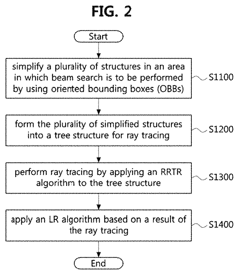
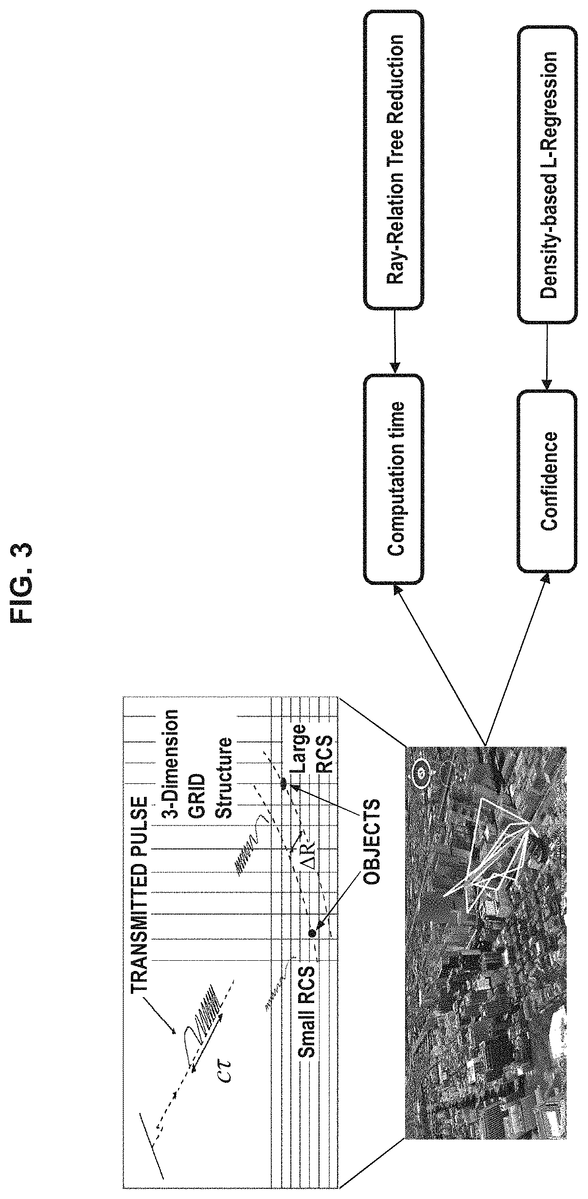
The patent describes an apparatus for selecting a path for transmitting maximum power from a base station to a terminal using a simplified tree structure. This structure is formed by using oriented bounding boxes and reducing the number of surfaces by utilizing normal vectors and vertices for triangles. The apparatus uses an algorithm for reducing computation load on the graphic processing unit and a linear regression algorithm for calculating the maximum power to be transmitted. This solution increases the amount of wideband data communication and allows for high-speed wideband data communication, regardless of the terminal's location. Additionally, the apparatus can estimate powers to be transmitted at all positions in the area.

Problems solved by technology

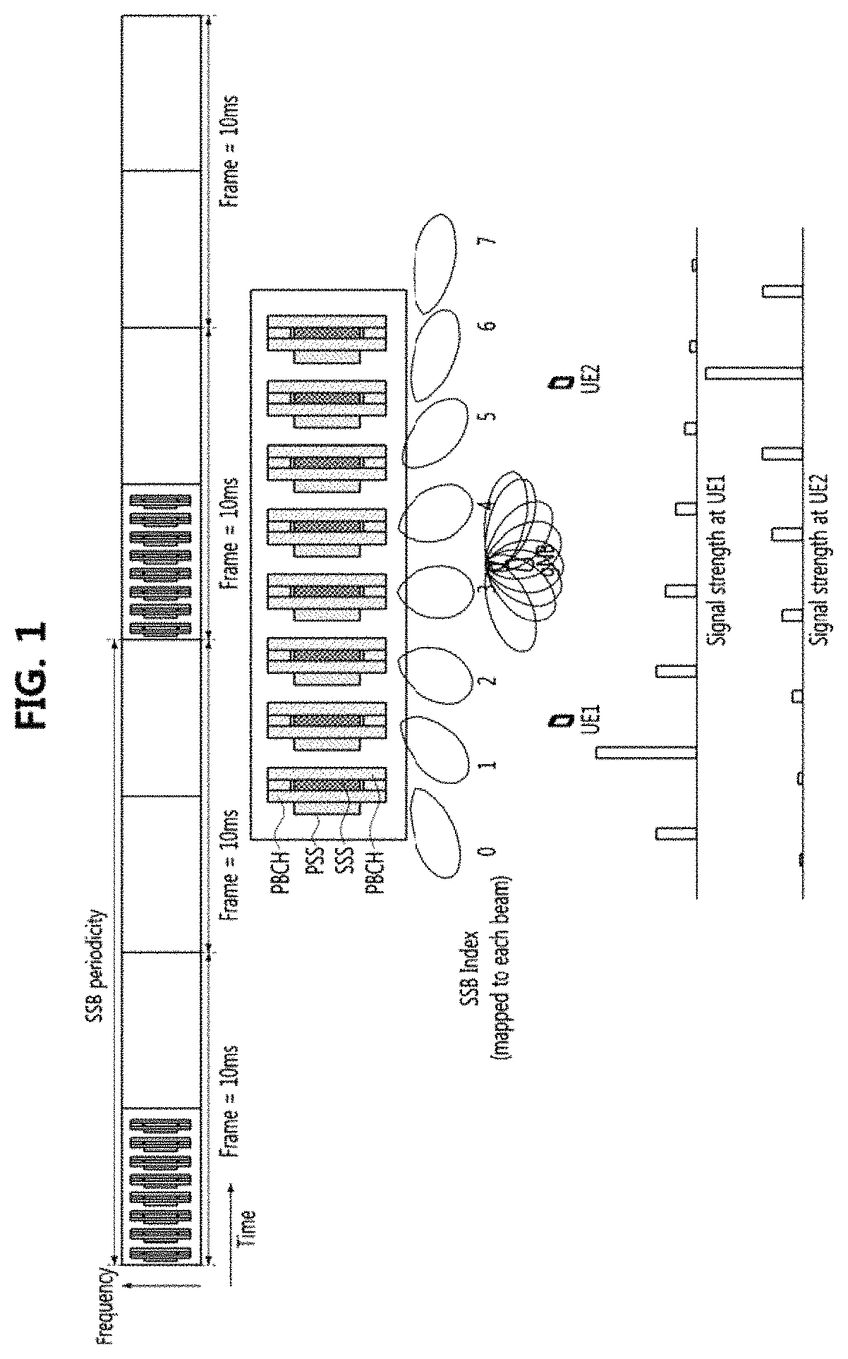
However, since the current 5G system has an SSB periodicity of 20 ms, there may be a problem of efficiency degradation in NR-5G communication services that require high-speed data communication.
Meanwhile, since the current 5G system periodically transmits beams in predetermined directions according to beam indices in order to increase coverage, there may be a problem in that the amount of computation for the beam search increases.
Further, the current 5G system has a problem in that when the terminal moves while performing wideband data communication, the data communication should be stopped and the SSBs should be transmitted again.
However, the conventional radar system has a problem in that it is difficult to accurately estimate the position of the target object when there are many reflectors around the target object or when the target object moves to a non-line of sight (NLOS) region.

Method used


Image

  • Apparatus and method for selecting path through beam search
  • Apparatus and method for selecting path through beam search
  • Apparatus and method for selecting path through beam search

Examples


Embodiment Construction

[0033]Embodiments of the present disclosure are disclosed herein. However, specific structural and functional details disclosed herein are merely representative for purposes of describing embodiments of the present disclosure. Thus, embodiments of the present disclosure may be embodied in many alternate forms and should not be construed as limited to embodiments of the present disclosure set forth herein.

[0034]Accordingly, while the present disclosure is capable of various modifications and alternative forms, specific embodiments thereof are shown by way of example in the drawings and will herein be described in detail. It should be understood, however, that there is no intent to limit the present disclosure to the particular forms disclosed, but on the contrary, the present disclosure is to cover all modifications, equivalents, and alternatives falling within the spirit and scope of the present disclosure. Like numbers refer to like elements throughout the description of the figure...


PUM


Abstract

A method of selecting a path for transmitting a maximum power from a base station to a terminal includes simplifying a plurality of structures in an area by using OBBs, the area being an area in which beam search is to be performed; forming the plurality of simplified structures into a tree structure for ray tracing; performing the ray tracing by applying a ray tracing relation tree reduction (RRTR) algorithm for reducing an amount of computation of a GPU to the tree structure; and applying a linear regression (LR) algorithm for calculating the maximum power to be transmitted from the base station to the terminal based on a result of the ray tracing.

Description

CROSS-REFERENCE TO RELATED APPLICATION[0001]This application claims priority to Korean Patent Application No. 10-2020-0160006 filed on Nov. 25, 2020 with the Korean Intellectual Property Office (KIPO), the entire content of which is hereby incorporated by reference.BACKGROUND1. Technical Field[0002]The present disclosure relates to a method and an apparatus for configuring a path for transmitting a power, and more specifically, to a method and an apparatus for selecting a path for transmitting a maximum power to a terminal through beam search.2. Description of Related Art[0003]Currently, the 5G system uses various beam search schemes to select a path for transmitting a maximum power from a base station to a terminal. For example, referring to FIG. 1, the 5G system transmits synchronization signal blocks (SSBs) in various directions according to beam indices determined at a 20 millisecond (ms) cycle in consideration of NR-5G network energy efficiency, and performs beam search within ...

Claims


Application Information

Patent Timeline
Patent Type & Authority Patents(United States)
IPC IPC(8): H04W52/06H04W52/38H04W48/16H04W56/00
CPCH04W52/06H04W48/16H04W52/38H04W56/001H04W52/367H02J50/20H04B7/0408H02J50/90
Inventor KIM, CHUNG SUPCHOI, SUNG WOONGLIM, JONG SOOHONG, JU YEONCHONG, YOUNG JUN
Owner ELECTRONICS & TELECOMM RES INST
Learn More