Mounting board and method of manufacture

a technology of mounting board and mounting plate, which is applied in the direction of fixed connection, non-printed electrical components of printed circuits, coupling device connections, etc., can solve the problems of complex process of arranging plurality of pedestals at given positions on printed board, complex process of controlling parts and assembling work, and high labor intensity of workers, so as to reduce the failure rate of mounting board and improve production efficiency , the effect of reducing the cos

Active Publication Date: 2011-08-11
SUMITOMO WIRING SYST LTD
View PDF7 Cites 4 Cited by
  • Summary
  • Abstract
  • Description
  • Claims
  • Application Information

AI Technical Summary

Benefits of technology

[0016]According to the third aspect, it is possible to avoid a failure in molding such as a void caused on account of accumulation of a molding material in the bent parts. In result, a rate in failure of the mounting board can be reduced, thereby lowering a cost and enhancing efficiency in production.
[0017]According to the present invention, since the plural pedestals are integrated by the coupling portions, handling of the pedestals can be improved in a process of producing the mounting board and efficiency in production can be enhanced. Since the plural pedestals are positioned on the printed board all together, the number of positioning steps can be reduced. In addition, the number of jigs to be used for positioning can be reduced.

Problems solved by technology

Secondly, distal ends of the terminals inserted into the through-holes are soldered to the through-holes to form the mounting board.
However, there is a problem associated with this mounting means of terminals by soldering, that is the process of positioning and arranging the respective terminals on the printed board is a complicated procedure.
However, since the plurality of pedestals must be positioned on the printed board, the process of arranging the plurality of pedestals at given positions on the printed board has proven to require significant time and manpower.
Therefore, the process of controlling the parts and assembling the work becomes complicated and troublesome.

Method used


Image

  • Mounting board and method of manufacture
  • Mounting board and method of manufacture
  • Mounting board and method of manufacture

Examples


Embodiment Construction

[0025]Referring now to the drawings, embodiments of a mounting board in accordance with the present disclosure will be described below.

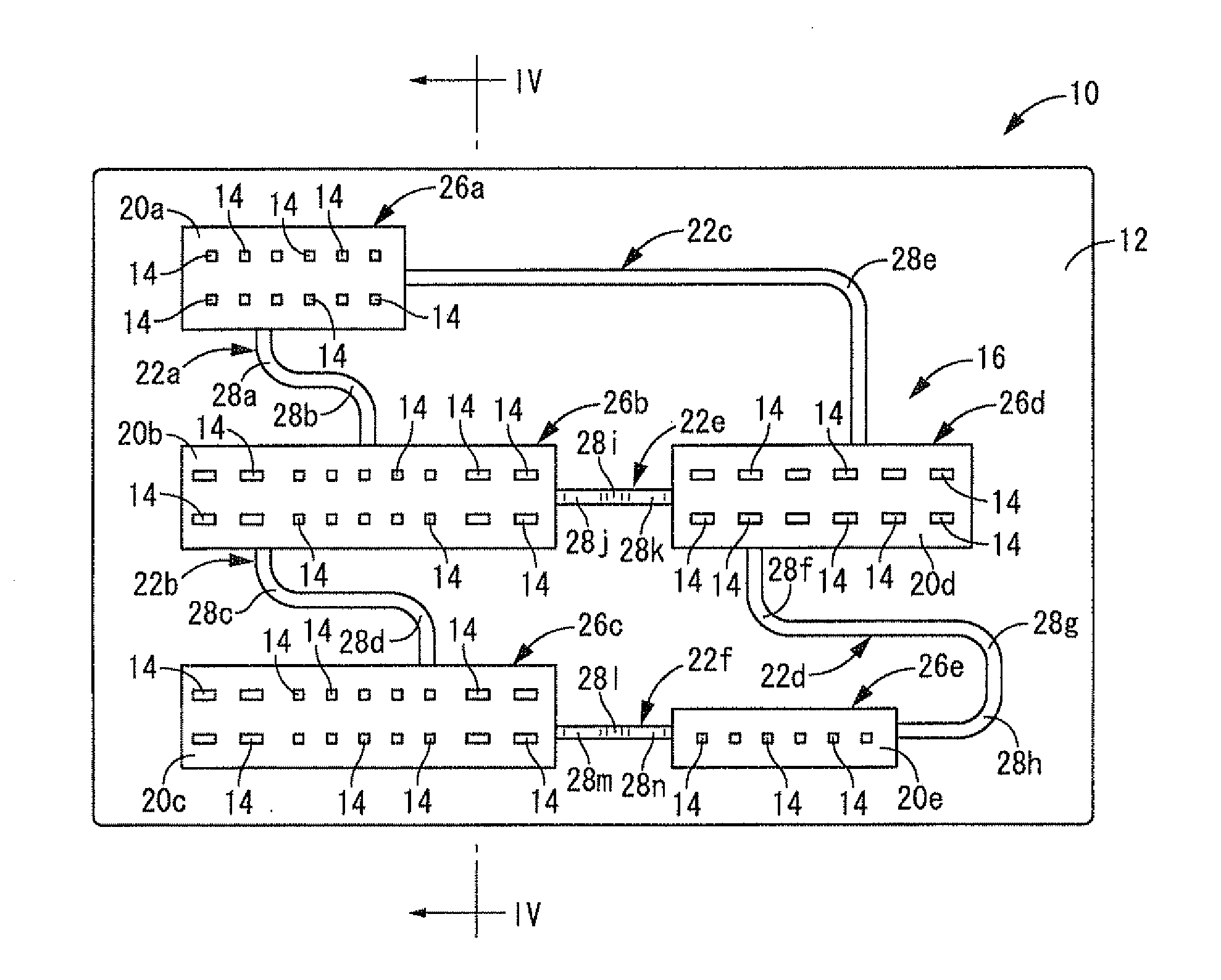
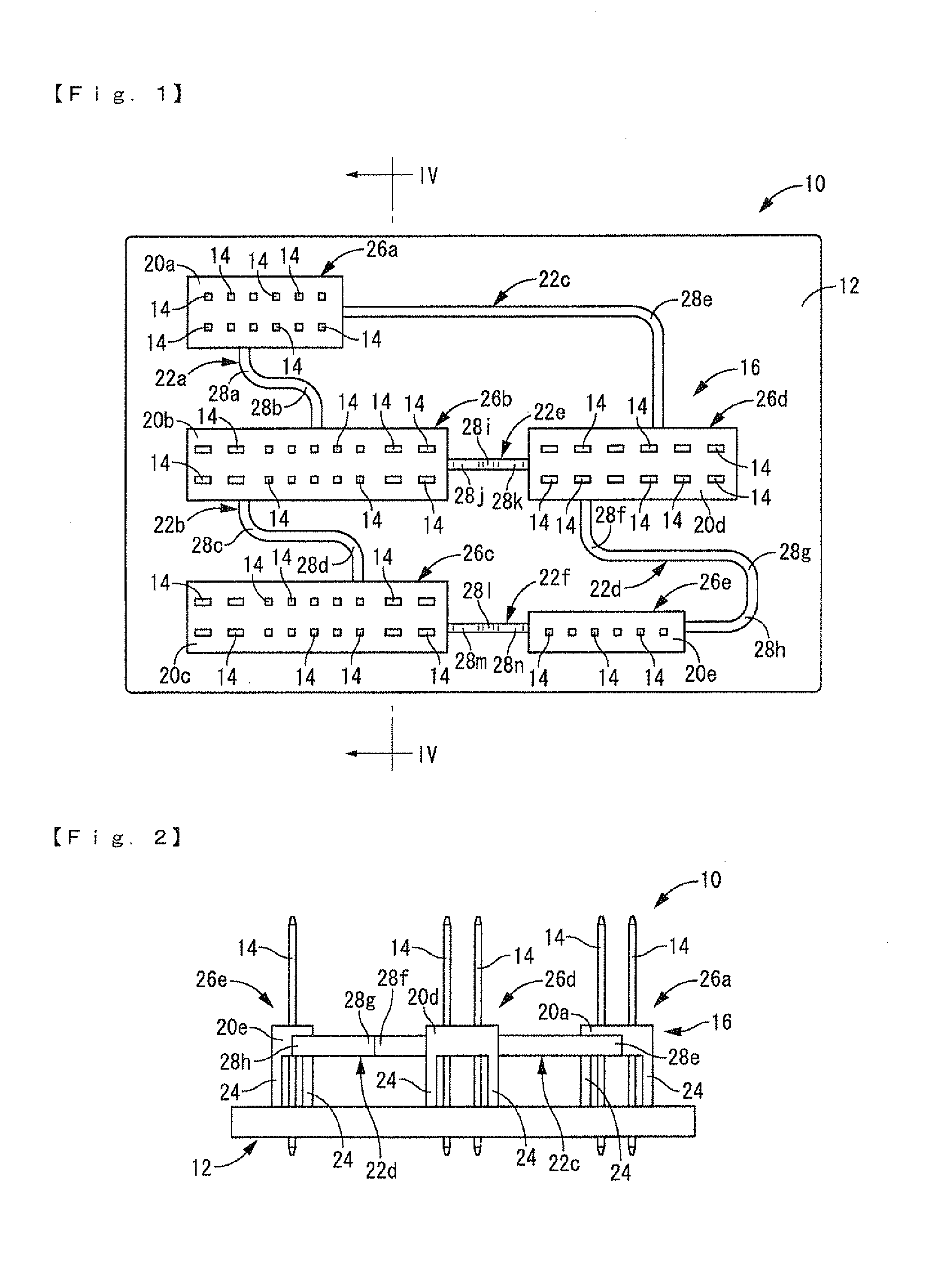
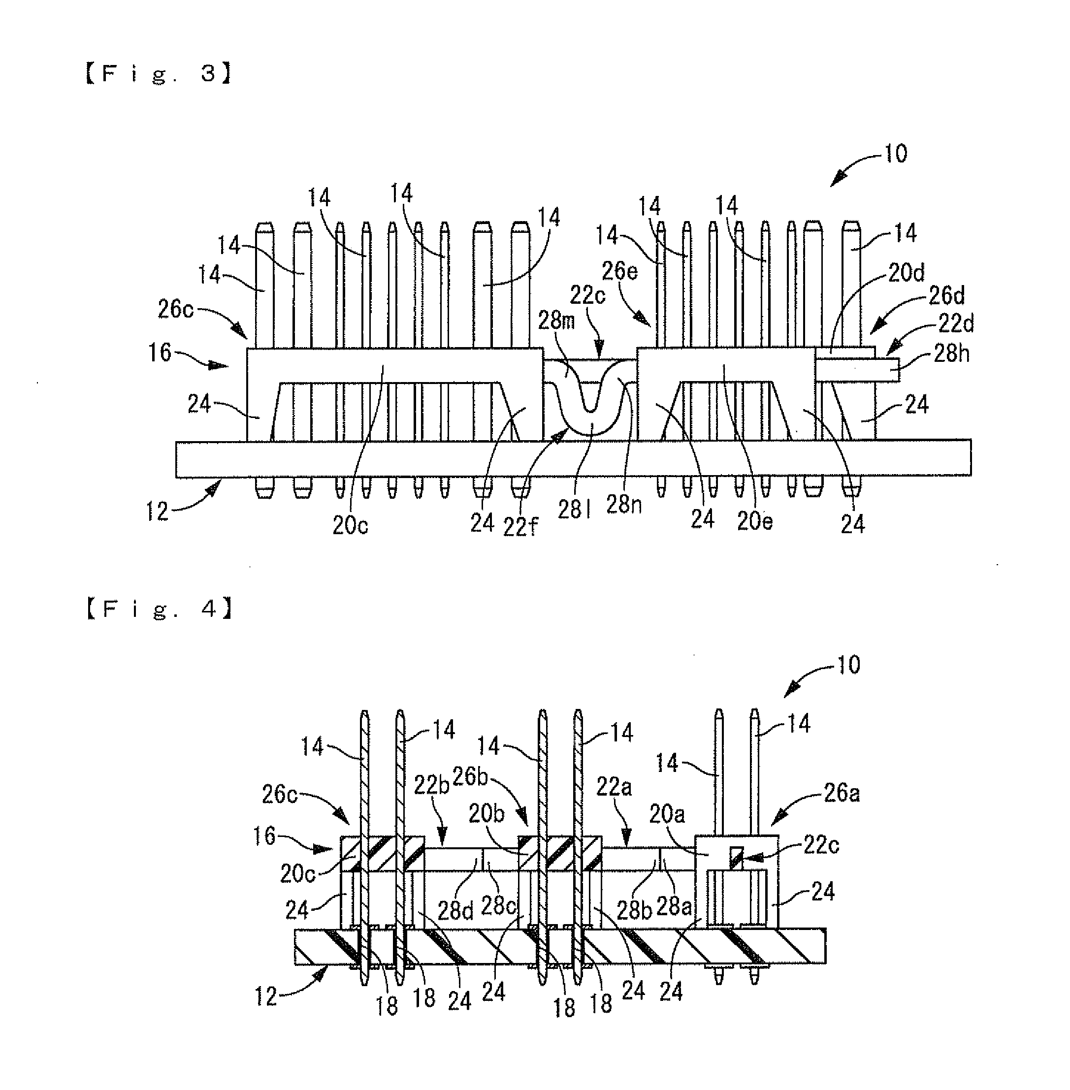
[0026]FIGS. 1 to 4 show a first embodiment of a mounting board 10 in accordance with the present disclosure. The mounting board 10 includes a printed board 12, terminal metal elements (terminals) 14 mounted on the printed board 12, and a pedestal plate 16. It should be noted in the following description in principle that upper and lower directions designate upper and lower directions in FIG. 1, right and left directions designate right and left directions in FIG. 1, and a vertical direction designates upper and lower directions in FIG. 2.

[0027]The printed board 12 includes an insulation board made of hard synthetic resin or the like, and an electrical circuit made of an electrical conductive material such as copper alloy and formed on the insulation board by printed wiring. The printed board 12 is provided with through-holes 18 (see FIG. 4) that exte...


PUM

PropertyMeasurementUnit
lengthaaaaaaaaaa
displacementsaaaaaaaaaa
shapeaaaaaaaaaa

Abstract

A mounting board having a plurality of terminals. The ends of each of the plurality of terminals are inserted into and soldered to through-holes positioned in a printed board, and the terminals are mounted on the printed board. A plurality of pedestals are disposed on one side of the printed board. The pedestals support the terminals. The pedestals are integrally coupled to one another through deformable coupling portions. Mutual displacements among the pedestals are allowed by the coupling portions.

Description

BACKGROUND[0001]1. Technical Field[0002]The present disclosure relates to a mounting board, in particular, to a mounting board in which terminals are soldered on a printed board.[0003]2. Background of the Disclosure[0004]Heretofore, a mounting board that electrically connects electrical components to terminals has been known. In the mounting board, terminals to be connected to electrical components such as fuses, relays, and connectors that are provided with terminals are mounted on a printed board. For example, the mounting board has been studied to be utilized in an electrical control unit (ECU) for a motor vehicle. JP 2008-35669 A, JP 2002-270986β, JP 2003-217437β, and JP HEI 10(1998) 106653 A disclose some examples of the mounting board.[0005]Heretofore, related art, that has been directed towards a means for mounting terminals on a printed board to connect electrical components to a printed board, have generally adopted soldering as the preferred fixing means. Firstly, the prin...

Claims


Application Information

Patent Timeline
Patent Type & Authority Applications(United States)
IPC IPC(8): H05K1/11H05K3/34H01R9/22H01R12/00H01R12/50H01R12/71H05K1/18
CPCH01R12/7082H01R12/91H05K3/306H05K3/3447Y10T29/49149H05K2201/10303H05K2201/10424H05K2201/10537H05K2201/10189
Inventor GOTO, HIDEKI
Owner SUMITOMO WIRING SYST LTD
Why Eureka
Try Eureka