Mixing device for tub

a technology for mixing devices and tubs, which is applied in the directions of mixing, transportation and packaging, physical therapy, etc., can solve the problems of decreased transparency of mixed liquid in the bath, increased pressure in the mixing chamber, so as to prevent the content of dissolved gas from dropping

Inactive Publication Date: 2008-05-15
MASUDA MASATOSHI
View PDF2 Cites 6 Cited by
  • Summary
  • Abstract
  • Description
  • Claims
  • Application Information

AI Technical Summary

Benefits of technology

[0007]An embodiment of the present invention was developed to solve at least one of the aforementioned problems, and in an embodiment, one of objects of the present invention is to provide a tub apparatus capable of minimizing the amount of bubbles generated by the mixed liquid in the tub.
[0025]According to the invention described in any one of Embodiments 8 to 10, drop in the content of dissolved gas due to pressure drop in the mixing chambers can be prevented.

Problems solved by technology

With this type of bath mixing apparatus, however, mixing of a large amount of gas into liquid creates the problem of the supplied mixed liquid generating bubbles in the bath.
If bubbles generate in the bath, the transparency of the mixed liquid in the bath decreases and the bath user also feels unpleasant.

Method used


Image

  • Mixing device for tub
  • Mixing device for tub
  • Mixing device for tub

Examples


embodiment 1

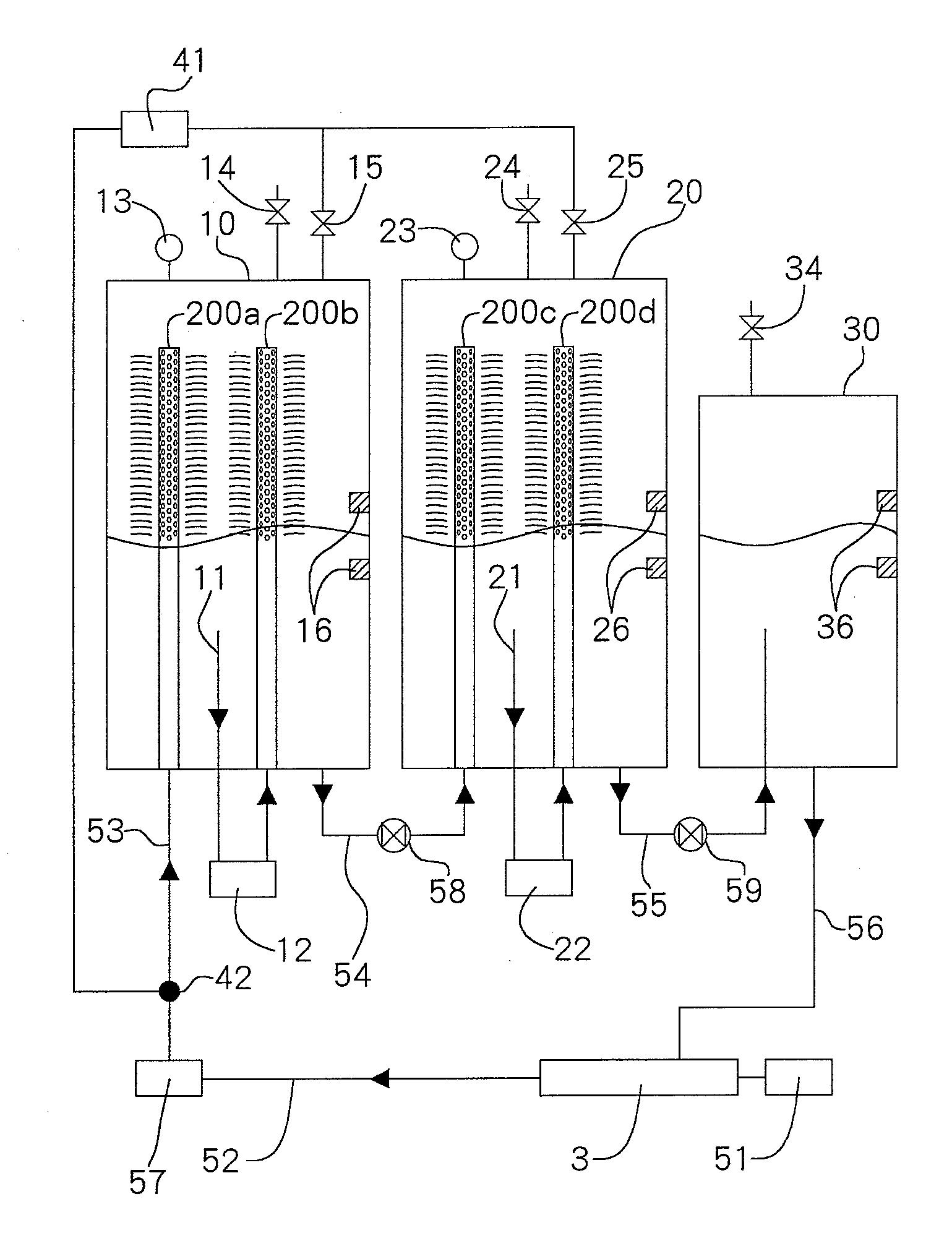
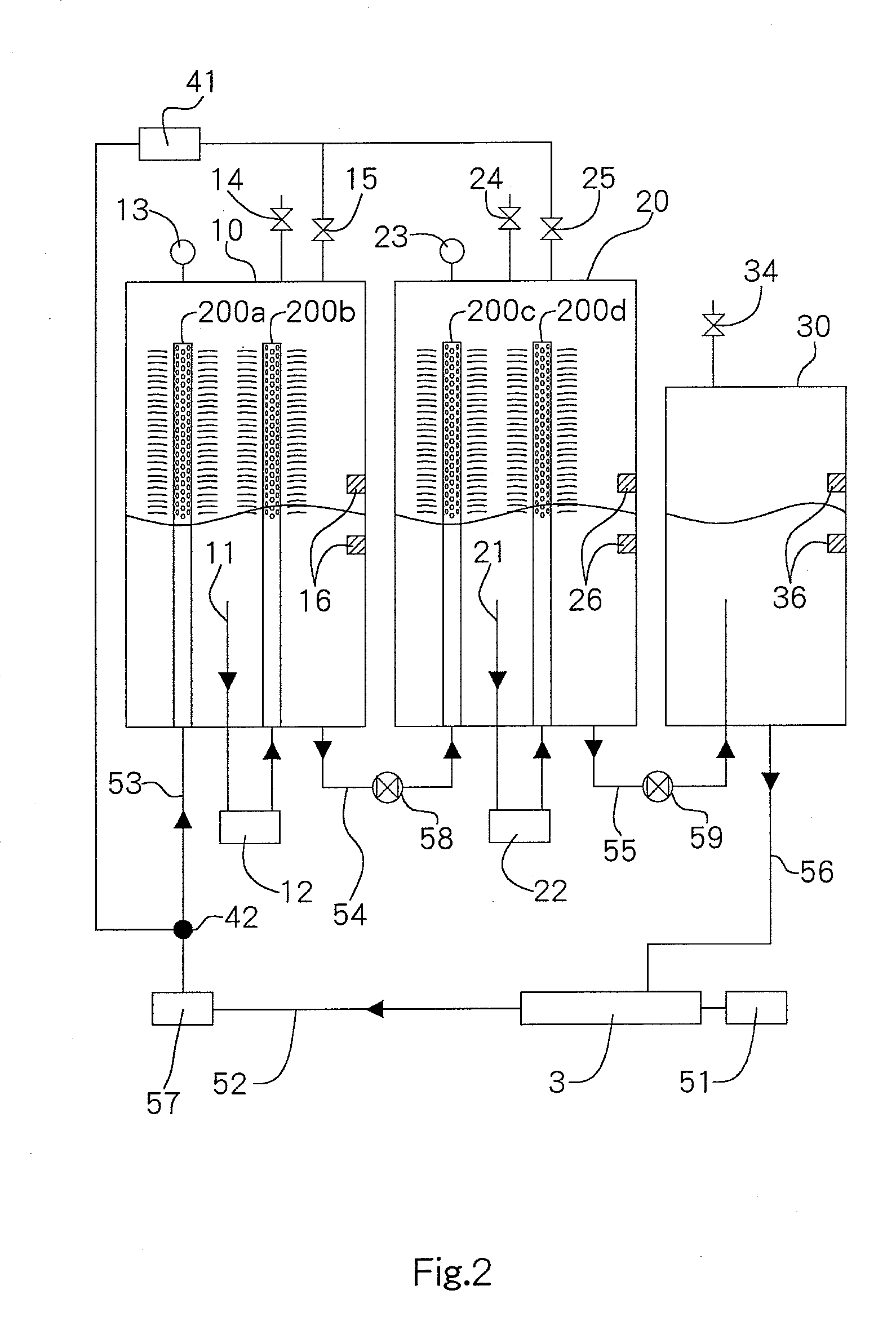
[0150]A bath mixing apparatus for supplying to a tub a mixed liquid comprising liquid mixed with gas, said bath mixing apparatus characterized by having: (i) a first mixing chamber having supply pipes through which mixed liquid is supplied, used to store mixed liquid at the bottom, and having a first internal pressure maintained at a level higher than the atmospheric pressure; (ii) a second mixing chamber having supply pipes through which mixed liquid is supplied, used to store mixed liquid at the bottom, and having a second internal pressure maintained at a level equal to or higher than the atmospheric pressure but lower than the first pressure in the first chamber; (iii) a mixed liquid circulation mechanism for circulating mixed liquid through the chambers in the order of the first mixing chamber and second mixing chamber and then returning it to the tub; (iv) a liquid supply part that supplies liquid to one of the mixed liquid circulation lines including the circulation lines for...

embodiment 2

[0151]A bath mixing apparatus according to Embodiment 1, further having: (I) a gas supply line that connects the first and second mixing chambers to the gas supply part via a valve; (II) sensors that measure the pressures in the first and second mixing chambers; and (III) a control part that controls the opening / closing of the valve based on the pressure values detected by the sensors.

embodiment 3

[0152]A bath mixing apparatus according to Embodiment 1 or 2, wherein a metering or chock valve is provided between the first mixing chamber and second mixing chamber, and also between the second mixing chamber and tub.


PUM

PropertyMeasurementUnit
sizeaaaaaaaaaa
sizeaaaaaaaaaa
sizeaaaaaaaaaa

Abstract

A fluid mixing apparatus configured to be connected to a tub, a liquid supply, and a gas supply, includes: a 1st pressurable liquid-storing chamber for storing liquid and mixing gas into liquid; a 2nd pressurable liquid-storing chamber for storing liquid and mixing gas into liquid; and a connection path connecting the 1st and 2nd liquid-storing chamber for supplying liquid from the 1st liquid-storing chamber to the 2nd liquid-storing chamber where the pressure inside the 2nd liquid-storing chamber is lower than the pressure inside the 1st liquid-storing chamber. The 2nd liquid-storing chamber is disposed downstream of the 1st liquid-storing chamber with respect to liquid flow.

Description

BACKGROUND OF THE INVENTION[0001]1. Field of the Invention[0002]The present invention generally relates to a fluid mixing device for a tub which mixes gas and liquid in order to supply a tub.[0003]2. Description of the Related Art[0004]The device in Japanese Patent Laid-open No. 2001-145676 is known as a device which mixes gas with liquid to supply this kind of tub. The device disclosed in Japanese Patent Laid-open No. 2001-145676 provides a tub, a jet nozzle which sprays a jet flow to a tub, and an air intake which connects to the jet nozzle by means of an air flow pipe. Thus, according to the device disclosed in Japanese Patent Laid-open No. 2001-145676, it is possible to supply liquid which has mixed with the gas in the tub, and it is possible to enhance the effect of a warm bath.[0005]However, for the device disclosed in Japanese Patent Laid-open No. 2001-145676, because there is simply only the supply of gas through the air flow pipe to the liquid which is to be supplied to the...

Claims


Application Information

Patent Timeline
Patent Type & Authority Applications(United States)
IPC IPC(8): B01F13/02B01F33/40
CPCA61H33/027A61H2033/0054A61H2201/5058A61H2201/5071B01F3/0473B01F5/106A61H33/60B01F13/1016B01F15/00155B01F15/00162B01F15/00253A61H2201/5007B01F13/1013B01F23/234B01F25/53B01F33/811B01F33/81B01F35/2113B01F35/2112B01F35/2209
Inventor MASUDA, MASATOSHI
Owner MASUDA MASATOSHI
Why Eureka
Try Eureka