[0025]It goes without saying that the present invention is not limited to the embodiments that have just been described, and that various simple alterations and variants could be envisaged by those skilled in the art, without departing from the scope of the present invention as defined by the annexed claims.
[0012]FIG. 1 is an exploded perspective view of a first embodiment of a timepiece according to the invention;
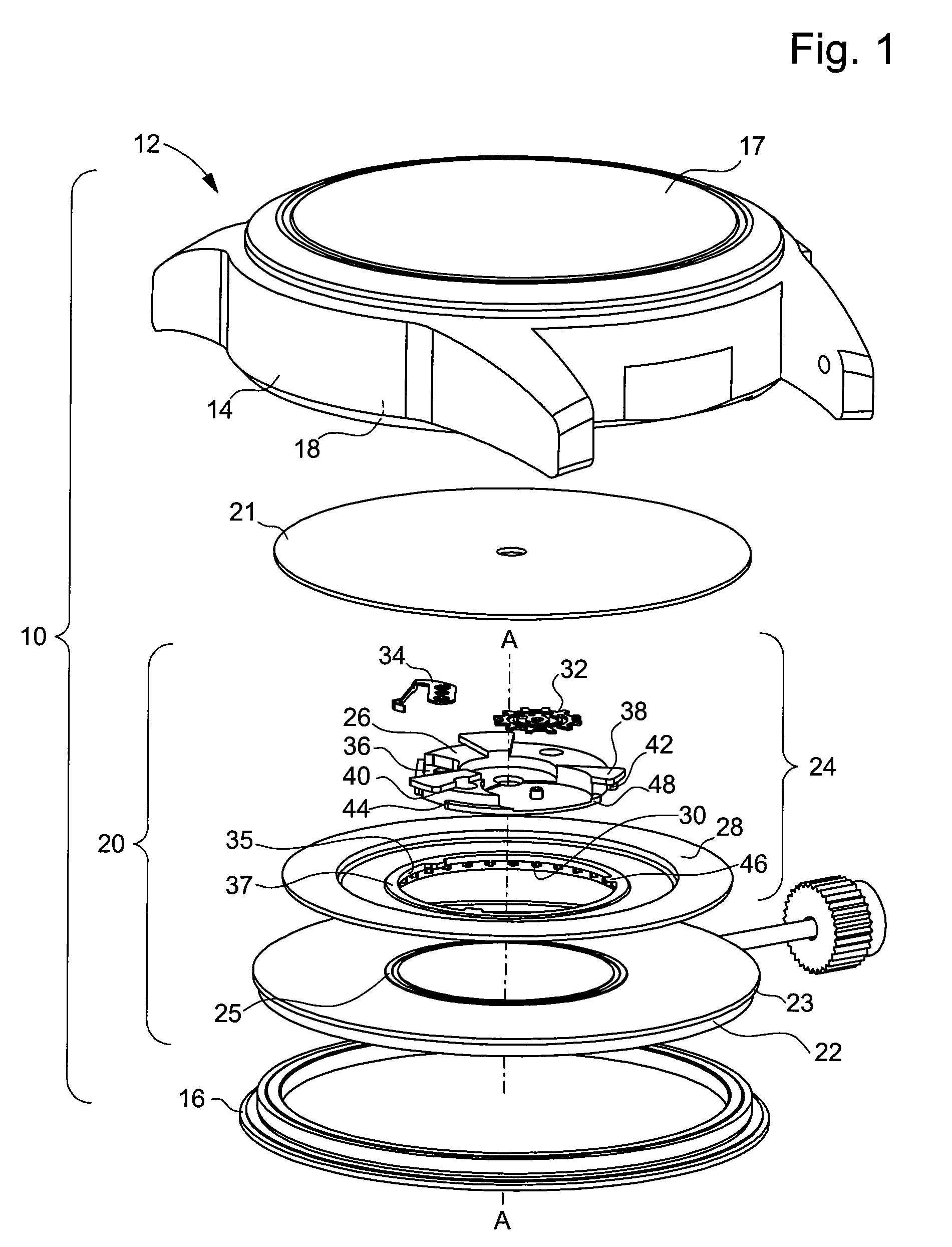
[0013]FIG. 2 is a partial cross-section of a movement fitted to said timepiece;
[0008]In a particularly advantageous embodiment, the bridge includes three positioning surfaces, and three
assembly surfaces, shifted axially and angularly relative to the positioning surfaces. The display member further includes three lugs. The contact surface, the positioning and assembly surfaces and the lugs are arranged so as to form together a bayonet assembly
system for mounting the display member on the bridge.
[0015]FIG. 4 is an exploded perspective view of a second embodiment of the invention according to the invention.
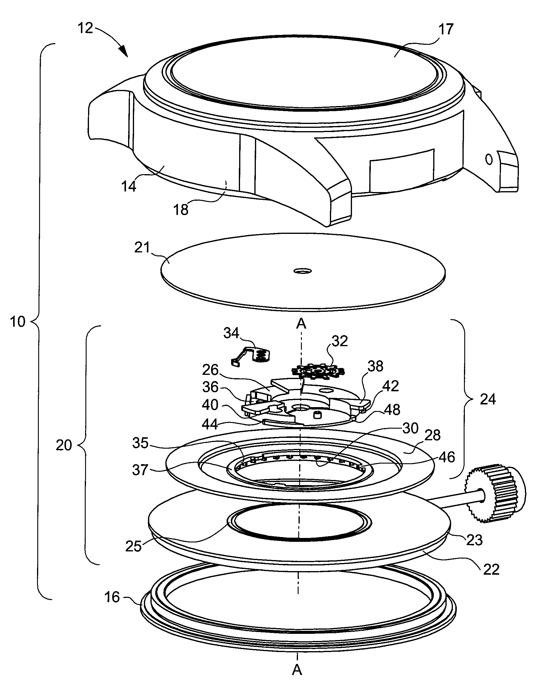
[0016]The timepiece shown in FIG. 1 and designated by the general reference 10 conventionally includes a case 12 formed of a middle part 14, a back cover 16 and a
crystal 17, together defining a housing 18 containing a movement 20, and a dial 21 inserted between
crystal 17 and movement 20.
[0017]Movement 20 is shown in cross-section in FIG. 2. It includes a fixed support 23, such as a bottom plate, on which are mounted the members of a basic movement 22, shown schematically in FIGS. 1 and 2, via a unit secured to said bottom plate. It further includes a display module 24, mounted on the top face of bottom plate 23. The “top face” means the face directed towards dial 21, and the “bottom face” means the opposite face. The method of securing bottom plate 23 to case 1 is not shown in FIGS. 1 and 2, but it could be achieved using screws, clips, a casing ring or any other means known to those skilled in the art. The top face of bottom plate 23 is provided with a circular
screw thread 25, the function of which will be specified below.
[0018]Display module 24 includes in a conventional manner a substantially circular central bridge 26 and a display ring 28 with an axis AA, coaxial to bridge 26, on which are affixed time indications, such as dates, days of the week, or even phases of the moon. Bridge 26 is rigidly secured to bottom plate 23 via screws that are not shown in FIGS. 1 and 2. Display ring 28 is mounted to rotate freely about bridge 26, abutting on bottom plate 26. For this purpose, it is provided with a substantially cylindrical portion 29 forming a
support surface 31 that cooperates with the
screw thread 25 so as to limit friction linked to its rotational movement. The cylindrical portion 29 is provided with a toothing 30 located on the inner flank thereof, for driving ring 28 in rotation. A
drive wheel 32, mounted to rotate freely on bridge 26 and drawing its drive force from a
kinematic chain driven by basic movement 22, cooperates with toothing 30. A
jumper spring 34, arranged in a recess 36 provided for this purpose on bridge 26, is for the angular positioning of ring 28. Display module 24 further includes, optionally, a correction device that is not shown, preferably mounted on the bottom face of bridge 26.
[0019]According to the invention, display ring 28 is provided on the side of the inner
diameter thereof, with an annular portion 35 extending radially above toothing 30 and forming a contact surface 37 oriented towards dial 21. Bridge 26 is provided, with three protruding portions 38 angularly distributed over the periphery thereof, and extending radially above contact surface 37. Said protruding portions 38 form three positioning surfaces 40 cooperating with contact surface 37 so as to position display ring 28 axially on bottom plate 23. Ring 28 is thus free in rotation and held axially, in one direction by bottom plate 23, and in the other direction by protruding portions 38.
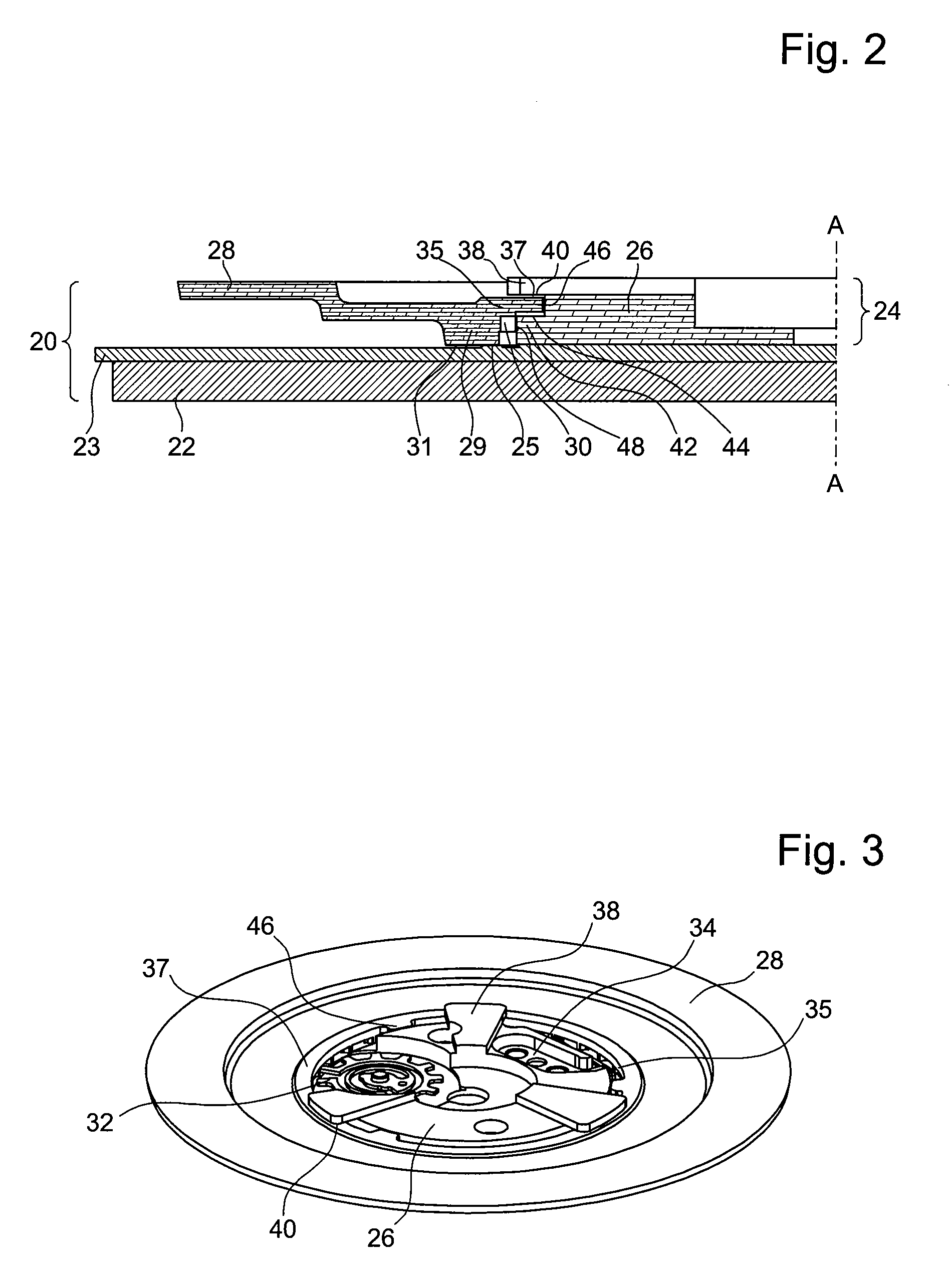
[0022]The pre-assembly of display module 24 is carried out as follows. Driven wheel 32 and
jumper spring 34 are positioned on bridge 26 and held axially by the aforementioned means. Display ring 28 is mounted on bridge 26 via the bayonet
system. For this purpose, lugs 46 are moved to face protruding portions 38, then ring 28 is rotated so as to bring lugs 46 opposite shoulders 42. In this angular position, and because the thickness of annular portion 35 is adapted to the
axial distance between protruding portions 38 and shoulders 42, contact surface 37 cooperates with positioning surfaces 40 and lugs 46 cooperate with assembly surfaces 44. As a result, ring 28 is axially positioned relative to bridge 26. The display module 24 thereby pre-assembled is shown in FIG. 3.
[0021]Bridge 26 is further provided with three shoulders 42, formed by annular portions that are shifted angularly and axially relative to protruding portions 38, and forming three assembly surfaces 44, oriented towards dial 21. For reasons that will appear below, the axial shift between shoulders 42 and protruding portions 38 is very slightly greater than the thickness of annular portion 35. The display ring 28 is, provided with three lugs 46 extending radially in the extension of annular portion 35, in the direction of axis AA. The assembly of annular portion 35—protruding portions 38—shoulders 42—lugs 46 forms a bayonet assembly
system one part of which, formed by shoulders 42 and lugs 46, has no function at the heart of the assembled timepiece 10, but is for mounting ring 28 on bridge 26, in order to form a pre-assembled display module 24. It will be noted that the flanks of shoulders 42 further form a rotational guide surface 48 for ring 28, cooperating with the end of toothing 30.

