Noise reducing device, noise reducing method, noise reducing program, and noise reducing audio outputting device

a technology of noise reduction and audio outputting device, which is applied in the direction of noise generation, ear treatment, instruments, etc., can solve the problems of increasing the scale of hardware configuration, increasing the cost, and unable to adapt to noise reduction, so as to prevent the scale of the circuit from becoming large, the configuration is simple and more advantageous in terms of cos

Inactive Publication Date: 2008-05-15
SONY CORP
View PDF11 Cites 103 Cited by
  • Summary
  • Abstract
  • Description
  • Claims
  • Application Information

AI Technical Summary

Benefits of technology

[0020]In this case, a hardware configuration suffices which only retains a plurality of parameters corresponding to a plurality of kinds of noise characteristics in the retaining section and has a selecting and setting section for selecting one of the parameters. Therefore the scale of the hardware configuration does not become large as compared with a case of using an analog filter circuit. That is, even when various noise characteristics are to be handled, it suffices only to retain a plurality of parameters corresponding to the various noise c

Problems solved by technology

The conventional active type noise reducing system has a problem of being unable to perform noise reduction adapted to the noise environment characteristic of a place where the noise reduction is to be performed.
However, the constitution in which the plurality of filter circu

Method used


Image

  • Noise reducing device, noise reducing method, noise reducing program, and noise reducing audio outputting device
  • Noise reducing device, noise reducing method, noise reducing program, and noise reducing audio outputting device
  • Noise reducing device, noise reducing method, noise reducing program, and noise reducing audio outputting device

Examples


first embodiment

Noise Reducing Device of Feedback Type

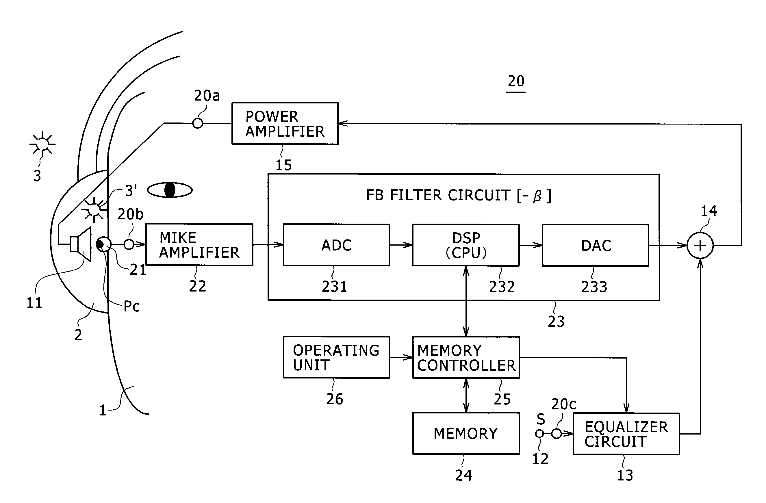
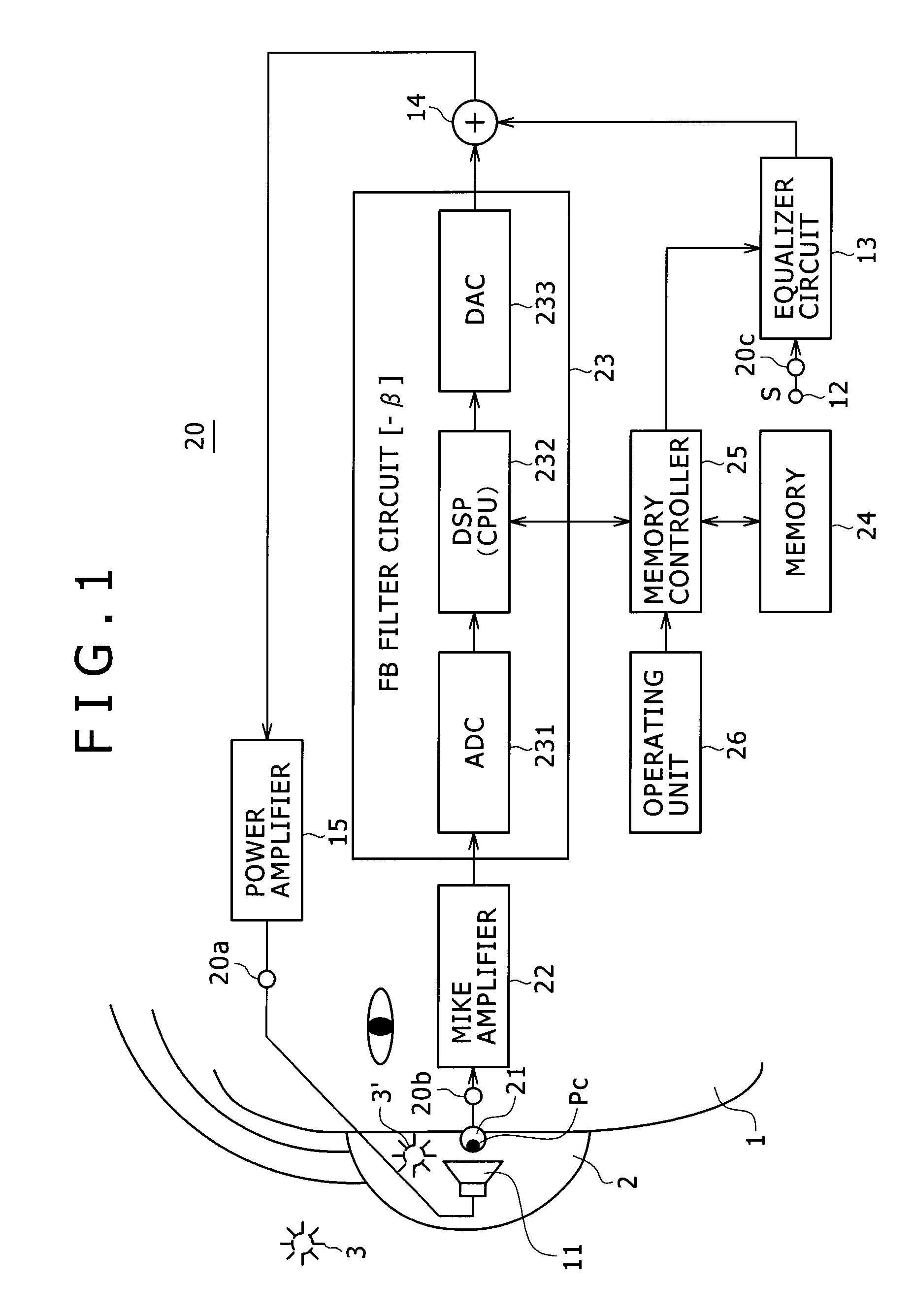
[0055]Description will first be made of an embodiment in which the present invention is applied to a noise reducing system of a feedback type. FIG. 1 is a block diagram showing an example of configuration of an embodiment of a headphone device to which an embodiment of the noise reducing device according to the present invention is applied.

[0056]For simplicity of description, FIG. 1 shows the configuration of only a part of the headphone device for the right ear side of a listener 1. The same is true for embodiments to be described later. Incidentally, it is needless to say that a part for a left ear side is configured in the same manner.

[0057]FIG. 1 shows a state in which the listener 1 wears the headphone device according to the embodiment and thereby the right ear of the listener 1 is covered by a headphone casing (housing unit) 2 for the right ear. A headphone driver unit (hereinafter referred to simply as a driver) 11 as electric-to-acousti...

second embodiment

Noise Reducing Device of Feed Forward Type

[0109]FIG. 7 shows an example of configuration of an embodiment of a headphone device to which an embodiment of the noise reducing device according to the present invention is applied. FIG. 7 is a block diagram representing a case where a feed forward system is adopted in place of the feedback system of FIG. 1. In FIG. 7, the same parts as in FIG. 1 are identified by the same reference numerals.

[0110]A noise reducing device section 30 includes a microphone 31 as acoustic-to-electric converting means, a mike amplifier 32, a filter circuit 33 for noise reduction, a memory 34, a memory controller 35, an operating unit 36, and the like.

[0111]As in the noise reducing device section 20 of the feedback type as described above, the noise reducing device section 30 is connected to a driver 11, the microphone 31, and a headphone plug forming an audio signal input terminal 12 by connecting cables. References 30a, 30b, and 30c denote a connecting termin...

third embodiment and fourth embodiment

[0138]In the first embodiment and the second embodiment described above, the filter circuit is digitized, and a plurality of kinds of filter coefficients are prepared in the memory. As required, an appropriate filter coefficient can be selected from the plurality of kinds of filter coefficients and then set in the digital filter.

[0139]However, the digitized FB filter circuit 23 and the digitized FF filter circuit 33 have a problem of delay in the A / D converter circuits 231 and 331 and the D / A converter circuits 233 and 333. This problem of delay will be described below with reference to the noise reducing system of the feedback type.

[0140]For example, when an A / D converter circuit and a D / A converter circuit having a sampling frequency Fs of 48 kHz are used as a common example, supposing that an amount of delay caused within the A / D converter circuit and the D / A converter circuit is 20 samples in each of the A / D converter circuit and the D / A converter circuit, a delay of a total of ...


PUM


Abstract

A noise reducing device includes: an acoustic-to-electric conversion section for collecting noise and outputting an analog noise signal; an analog-to-digital conversion section for converting the analog noise signal into a digital noise signal; and a digital processing section for generating a digital noise reducing signal on a basis of the digital noise signal and a desired parameter. The device further includes: a retaining section for retaining a plurality of parameters corresponding to a plurality of kinds of noise characteristics; a setting section for setting one of the plurality of parameters as the desired parameter of the digital processing section; a digital-to-analog conversion section for converting the digital noise reducing signal into an analog noise reducing signal; and an electric-to-acoustic conversion section for outputting noise reducing sound on a basis of the analog noise reducing signal.

Description

CROSS REFERENCES TO RELATED APPLICATIONS[0001]The present invention contains subject matter related to Japanese Patent Application JP 2006-307364, filed in the Japan Patent Office on Nov. 14, 2006, the entire contents of which being incorporated herein by reference.BACKGROUND OF THE INVENTION[0002]1. Field of the Invention[0003]The present invention relates to a noise reducing device, a noise reducing method, a program for noise reduction processing, and a noise reducing audio outputting device.[0004]2. Description of the Related Art[0005]With the spread of portable type audio players, a noise reducing system that reduces noise of an external environment and thus provides a listener with a good reproduced sound field space in which the external noise is reduced has begun to be spread for headphones and earphones for the portable type audio players.[0006]An example of this kind of noise reducing system is an active type noise reducing system that performs active noise reduction and w...

Claims


Application Information

Patent Timeline
IPC IPC(8): H03B29/00
CPCG10K2210/1081G10K11/178H04R1/1083G10K2210/3013G10K2210/3033G10K2210/30391G10K2210/3042G10K2210/3222G10K2210/509H04R2460/01G10K11/17873G10K11/17823G10K11/17833G10K11/17879G10K11/1783G10K11/17825G10K11/17885G10K11/17875G10K11/17881
Inventor ASADA, KOHEI
Owner SONY CORP
Why Eureka
Try Eureka