

Image forming apparatus capable of forming high-quality image
a technology of high-quality images and forming apparatuses, applied in electrographic process apparatus, instruments, optics, etc., can solve the problems of insufficient detection of toner patterns, difficult to maintain constant image density, and noise in detection
- Summary
- Abstract
- Description
- Claims
- Application Information
AI Technical Summary
Benefits of technology
Problems solved by technology
Method used
Image


Examples
first embodiment
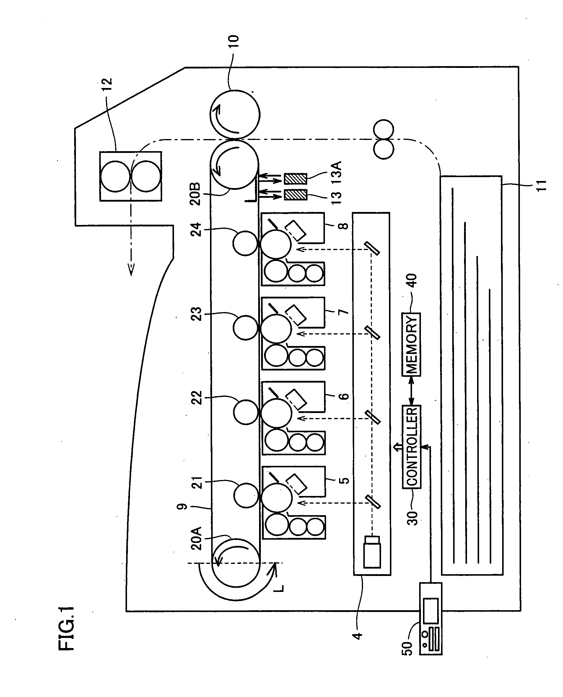
[0059]A function for performing the processing for updating the tone correction table in image stabilization control shown in FIG. 5 is attained mainly in controller 30 as a result of operation by controller 30 to read and execute an image stabilization control program stored in memory 40. Alternatively, some of the functions shown in FIG. 5 may be attained by the hardware configuration of printer 100 shown in FIGS. 1 and 2.
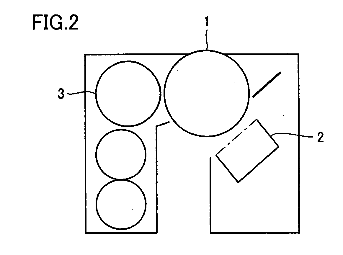
[0060]Referring to FIG. 5, the functions of printer 100 above are configured to include a toner pattern generation unit 101 generating the toner pattern representing a tone correction pattern on intermediate transfer belt 9, a toner pattern detection unit 103 detecting the toner pattern generated on intermediate transfer belt 9 by toner pattern generation unit 101, a determination unit 105 determining an abnormality region which will be described later based on the detection value, a curve approximation unit 107 subjecting an abnormality region out of the detecti...
second embodiment
[0083]Printer 100 according to the second embodiment further includes a density sensor 13A in addition to the hardware configuration described previously with reference to FIG. 1. In addition, in the second embodiment, as shown in FIG. 12, a mark 14 used for subsequent processing is provided on intermediate transfer belt 9. Mark 14 indicates a reference position on intermediate transfer belt 9, and should only have a color different from the surface of intermediate transfer belt 9 or reflectivity different from intermediate transfer belt 9. In order to avoid erroneous detection in the processing for detecting the toner pattern described previously, as shown in FIG. 12, mark 14 is preferably provided outside an image forming region on intermediate transfer belt 9.
[0084]Similar to toner density detector (density sensor) 13 described previously, density sensor 13A detects density of the color of the surface of intermediate transfer belt 9 for example by receiving reflected light from t...
third embodiment
[0100]In the first and second embodiments, the detection values in a wider range, namely, a range expanded toward lower and higher sides of the input tone, than the range determined by determination unit 105 as corresponding to the range on intermediate transfer belt 9 where the abnormality is present, are subjected to curve approximation by curve approximation unit 107. Therefore, the detection value without containing noise, which is the detection value located at the end portion of the range subjected to curve approximation, is used as the boundary condition for curve approximation.
[0101]Meanwhile, if determination unit 105 determines that noise is contained in the detection value at the end portion of the detection values, namely, at the end portion of a highlight portion where the input tone attains to the minimum value (0 in the present example) and the detection value attains to the largest value (an amount of reflected light is great) or at the end portion of a shadow portio...
PUM
 Abstract
Description
Claims
Application Information