

Pump
- Summary
- Abstract
- Description
- Claims
- Application Information
AI Technical Summary
Benefits of technology
Problems solved by technology
Method used
Image

Examples
first embodiment
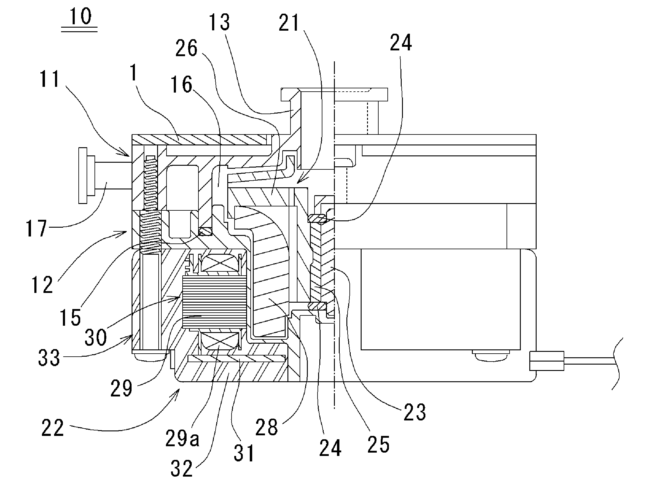
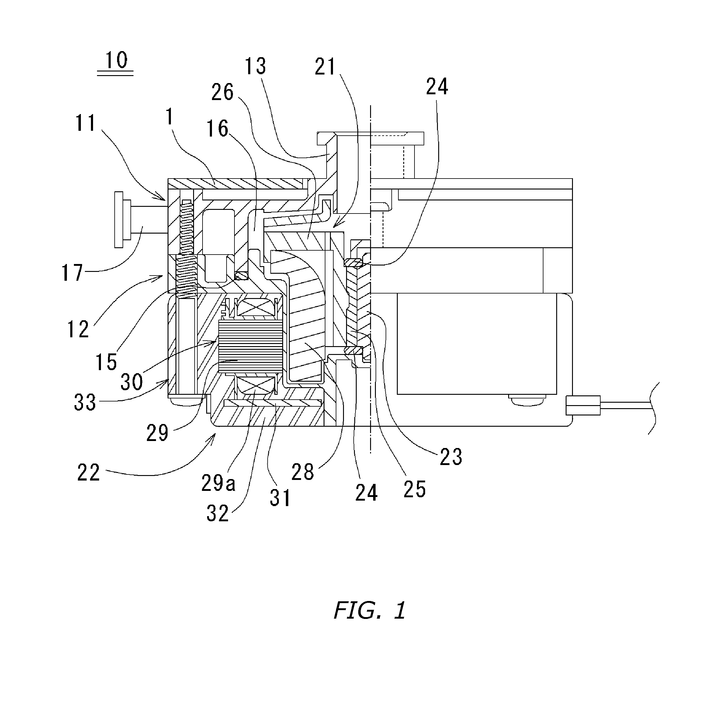
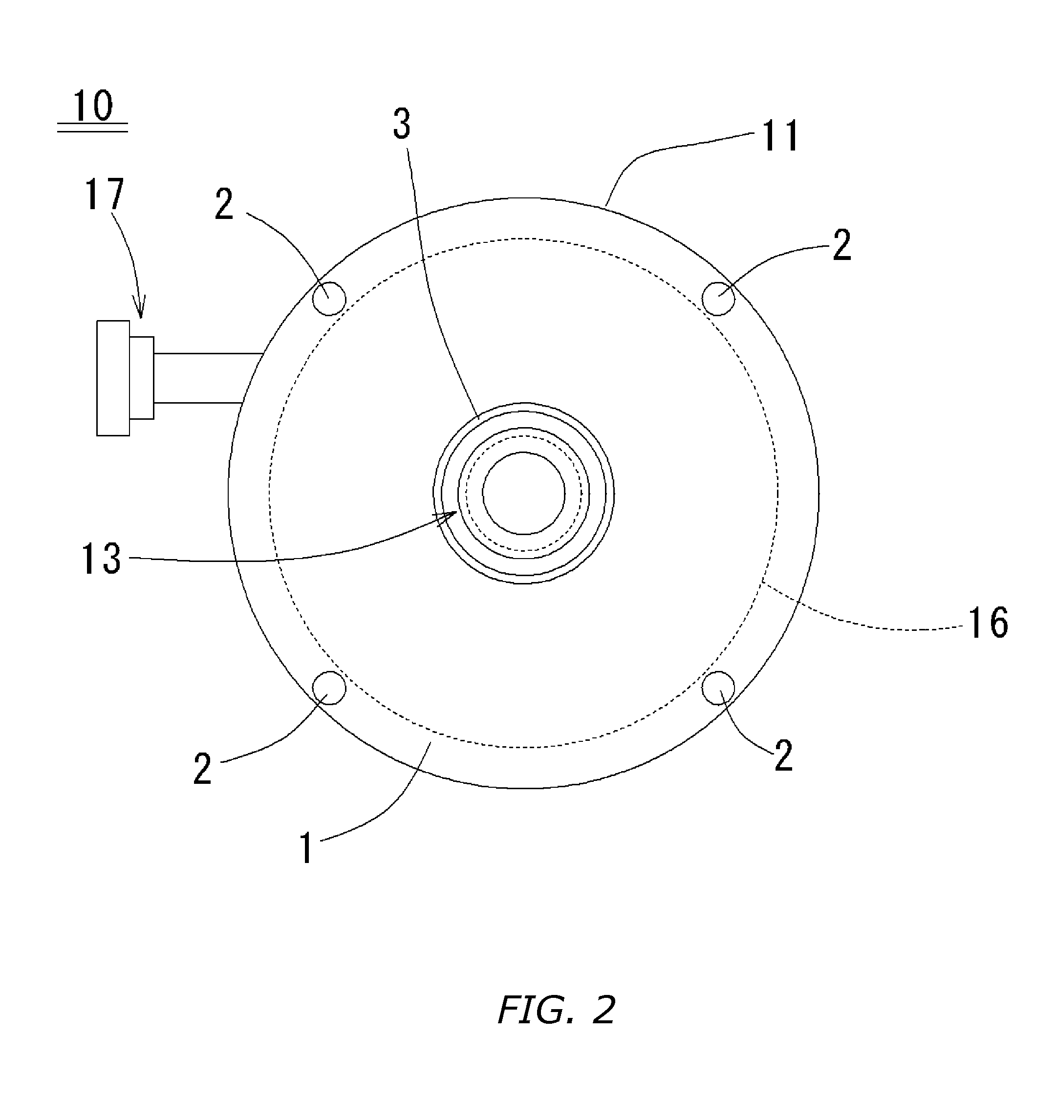
[0028]FIG. 1 is a diagram showing a schematic cross sectional view in an axial direction of a pump 10 according to a first embodiment of the present invention. FIG. 2 is a plan view of FIG. 1. As shown in FIG. 1, the pump 10 comprises: an upper case 11 and a lower case 12, which are formed of a resin material; a rotor 21 which rotates around a predetermined central axis J1, and which is located in a space generated between the upper case 11 and the lower case 12 which are joined together; and a ring shaped stator 22 which is located along an outer circumference of the rotor 21 and outside of the lower case 12. The pump 10 is commonly referred to as a canned type pump wherein the lower case 12 is provided between the rotor 21 and the stator 22. Note that, in the description of the preferred embodiments of the present invention herein, words such as upper, lower, left, right, upward, downward, top, and bottom for describing positional relationships between respective members and direc...
second embodiment
[0041]Next, a pump according to a second embodiment of the present invention will be described with reference to FIG. 3. FIG. 3 is a diagram showing a plan view, as seen from a side of, a pump according to a second embodiment of the present invention. In FIG. 3, elements similar to those illustrated in FIG. 1 are denoted by similar reference numerals, and description thereof is omitted.
[0042]In the first embodiment, the metallic cover 1 covers over only the top surface in the axial direction of the upper case 11. In the second embodiment, however, a metallic cover is provided on both top and bottom surfaces of a pump 70 so as to sandwich, and to provide additional durability, to the pump 70. That is, according to FIG. 3, a metallic cover 71 which covers over a top surface of the upper case 11 and a resin mold compound side metallic cover 72 which covers over a bottom surface of the resin mold compound 33 are provided on the upper case 11. The metallic cover 71 and the resin mold com...
third embodiment
[0047]FIG. 4 is a diagram showing a schematic cross sectional view in the axial direction of a pump 50 according to a third embodiment of the present invention. FIG. 5 is an enlarged view of a portion A shown in FIG. 4. As shown in FIG. 4, the pump 50 is a canned type pump, wherein the pump 50 has a common structure as the pump 10 according to the first embodiment. In FIG. 4, elements similar to those illustrated in FIG. 1 are denoted by similar reference numerals, and the description of the structure of the pump 50 is omitted.
[0048]The pump 50 according to the third embodiment comprises a stator 22 including an annular shaped resin mold compound 34 having therein the molded resin 32 in which the armature 30 and the printed circuit board 31 are provided. In the armature 30, the ring shaped laminated core 29 and the coil 29a are provided.
[0049]The resin mold compound 34 includes therein an annular shaped reinforcement board 5 which is formed of a metal plate. The reinforcement board ...
PUM
| Property | Measurement | Unit |
|---|---|---|
| Length | aaaaa | aaaaa |
| Shape | aaaaa | aaaaa |
| Internal pressure | aaaaa | aaaaa |
Abstract
Description
Claims
Application Information