Flexible Material and Method of Manufacturing the Flexible Material

a flexible material and manufacturing method technology, applied in the field of flexible materials and manufacturing methods, can solve the problems of affecting the wearer's comfort, lagging soft pads associated with hard shells, and pads with hard surfaces or shells facing the wearer, etc., to mitigate the effect of hard impact on the padding, dissipate the force impinging on the padding, and reduce the impact of hard shells

Inactive Publication Date: 2008-05-15
STIRLING MOLDINGS
View PDF99 Cites 105 Cited by
  • Summary
  • Abstract
  • Description
  • Claims
  • Application Information

AI Technical Summary

Benefits of technology

[0005]The above described needs are met in accordance with flexible protective padding material described herein. The flexible protective padding material comprises an array of resilient multilayered elements or blocks which have generally planar top and bottom surfaces and each of which have at least two layers which include a first layer bonded to an outer second layer. The first layer worn next to the body has a first compressibility of at least about 110 kPa at deflection of 50% and a first density of at least 30 kg/m3; and the second or outer layer has a second compressibility of at least about 400 kPa at deflection of 50% and a second density of at least 90 kg/m3, the second layer denser than the first layer and not being as compressible as the first layer. The total compressibility of each element with the at least two layers, the spacing between the elements and the total thic

Problems solved by technology

The foam elements of the '325 patent, however, are not arrayed and sufficiently stiff to dissipate a hard or extremely violent blow to the surface of the padding.
Pads with a hard surface or shell which has padding facing the wearer, however, have lacked flexibility because of the continuou

Method used


Image

  • Flexible Material and Method of Manufacturing the Flexible Material
  • Flexible Material and Method of Manufacturing the Flexible Material
  • Flexible Material and Method of Manufacturing the Flexible Material

Examples


Embodiment Construction

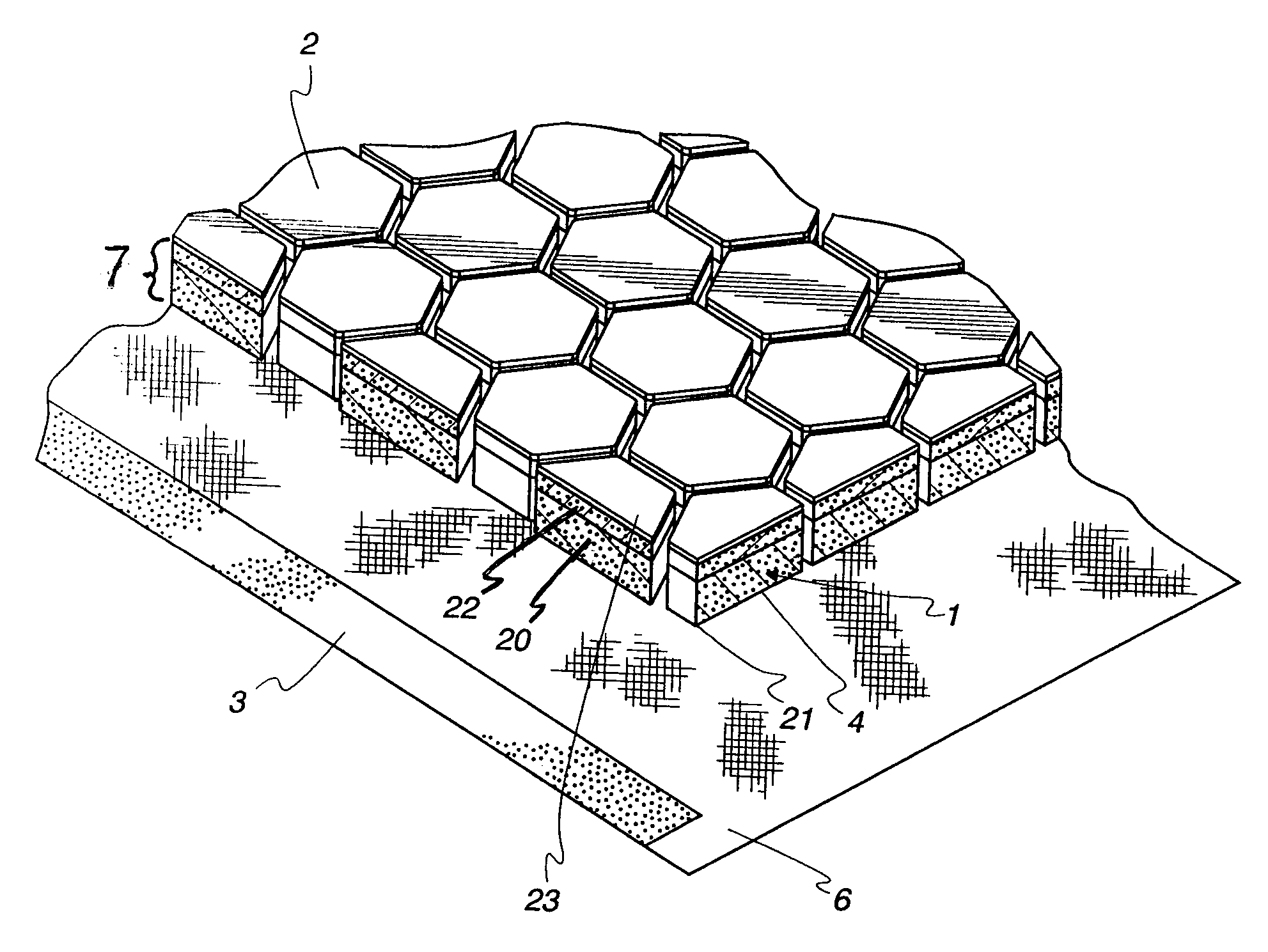
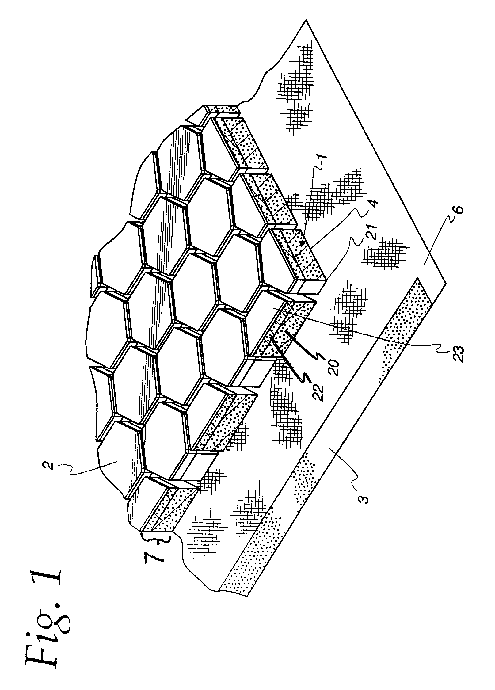
[0028]Referring to FIG. 1, the flexible material comprises a plurality of resilient multilayered hexagonal blocks 1 of a resilient closed-cell polyethylene foam, having sides of approximately 14 mm long and 12 m thick, joined with a hot melt adhesive to a fabric substrate 6. Each multilayered resilient hexagonal block is formed of two planar layers of hexagonal cross sections 2 and 4 of closed cell polyethylene foam bonded together. In FIG. 1, the layer bonded to substrate 6 is represented by the numeral 20 and the outer layer is represented by numeral 22. These layers form a laminate 7 and are referred to herein as bottom layer 20 and top layer 22 due to their positioning in FIG. 1. Top foam layer 22 has a density greater than the density of bottom layer 20, but the top layer is not as compressible as the bottom layer. In the present example both layers comprise closed cell foam. The first layer of foam should have a density of from about 30 to about 50 kg / m3, a compressibility of ...


PUM

PropertyMeasurementUnit
Lengthaaaaaaaaaa
Lengthaaaaaaaaaa
Lengthaaaaaaaaaa

Abstract

A flexible protective padding material is described and comprises an array of resilient multilayered elements or blocks which have generally planar top and bottom surfaces and each of which have at least two layers which include a first layer bonded to an outer second layer. The total compressibility of each element with the at least two layers, the spacing between the elements and the total thickness of the elements provides the elements with the ability to compress such that at least one side wall of each of adjacent elements move together and touch each other to provide a joined outer surface of elements which dissipates a blow to the protective padding.

Description

FIELD OF THE INVENTION[0001]This application relates to a material which combines compressibility, density and flexibility for use as protective padding, especially for protection of the human body during sports, or other physical activity which exposes the body to impact injuries. This application also relates to garments which incorporate the flexible material and a method of making the flexible material.BACKGROUND OF THE INVENTION[0002]Protective wear and protective material conventionally comprise pads associated with fabric, often a stretch fabric, where the pads and fabric are inserted into pockets or sewn onto the garment or substrate. Often the padding or foam is perforated to permit or improve the wicking of perspiration from the body during strenuous physical activity. U.S. Pat. No. 5,689,836 to Fee et. al. describes such foam padding associated with a stretch garment.[0003]U.S. Pat. No. 6,743,325 to Taylor describes a flexible material where a resilient polymeric foam mat...

Claims


Application Information

Patent Timeline
IPC IPC(8): B32B3/16B32B7/02B32B7/022
CPCA41D31/005A63B71/08A63B71/10A63B71/12A63B71/1225Y10T428/163A63B2209/00B32B5/32F41H1/02F41H5/04A63B2071/1208A41D31/285B32B7/022B32B7/02A41D13/05A41D13/08B32B3/16B32B2571/00B32B2571/02B32B5/18B32B5/245
Inventor TAYLOR, DAVID STIRLING
Owner STIRLING MOLDINGS
Why Eureka
Try Eureka