
Process and device for monitoring a patient

Active Publication Date: 2008-05-15
DRAGERWERK AG
View PDF15 Cites 1 Cited by
  • Summary
  • Abstract
  • Description
  • Claims
  • Application Information

AI Technical Summary

Benefits of technology

[0006]The process according to the present invention comprises the step of selecting at least one parameter value from the plurality of parameter values, where the at least one parameter value selected is displayed by means of the display means in a way that differs from the manner of display of the parameter values not selected from the plurality. Thus, weighing of the significance or relevance of certain parameter values is thus performed according to the present invention, which makes possible for the person monitoring the patient a more direct, more rapid and more effective access to the parameter values that are actually relevant for the monitoring from the plurality of parameter values determined on the basis of the special display of these parameter values. A first, direct, essential advantage of the present invention is therefore the increased reliability in monitoring the patient.
[0007]Since the person monitoring the patient, which person may be, for example, the anesthesiologist in charge in case of monitoring the anesthesia of the patient by means of a so-called monitor, has to deal according to the present invention only with the selected, comparatively few parameter values, the use of the process according to the present invention is less demanding in terms of attention and concentration. This enables that person to work with less fatigue and ultimately leads, in turn, to increased safety for the patient based on a less stressed caregiver or monitoring person, who will make fewer errors in estimating or evaluating the patient's status based on the selection of relevant parameter values.
[0008]The selection of certain parameter values may be performed according to clinical points of view. For example, a currently measured threshold limit value (TLV) is more relevant in case of the monitoring of anesthesia than a TLV which was measured hours before during the same anesthesia but is often still displayed in the display means. The same statement is also true of the heart rate, the respiration rate, the oxygen saturation and the like during the monitoring of a patient by means of a corresponding monitor. A selection can be made by the person skilled in the art manually or at the factory in this case as well, according to which, for example, only the last x values and / or only values that are below or exceed a predetermined parameter range, and / or only values that come correspondingly close to a certain parameter range, are selected for special display.
[0009]One possibility of displaying selected parameters in a special manner, which differs from the manner of display of non-selected parameter values, is the use of different contrasting. Another possibility is to use different colors. For example, signal colors may be used for selected parameter values, which require special attention of the monitoring physician or caregiver.
[0010]The special manner of display of selected parameter values may, however, also consist of displaying only the selected parameter values, whereas non-selected parameter values are not visible at all in a basic setting of the display means when the process according to the present invention is being carried out.
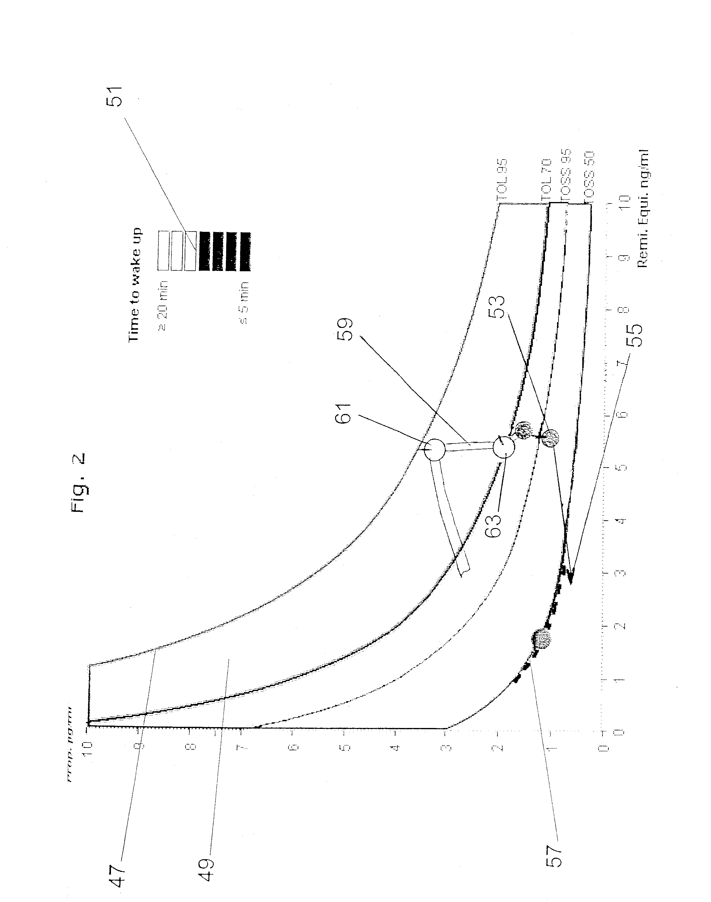
[0011]Such a display could be performed, independently from other features of the process according to the present invention, for example, by the functioncolor(t)=(15−t) / 15 for 0 min<=t<=15 min; andcolor(t)=0.0 for t>=15 min  (1)in which [t]=min, 1.0 for white and 0.0 for black on a dark background. The term “color” being able to be used according to the present invention for a contrast difference between lighter and darker display or for an actual color.

Problems solved by technology

The physician caring for the patient being monitored or the caregiver of the patient being monitored is therefore faced with the often rather complex task of recognizing the state of monitoring of this patient at a current given point in time sufficiently, rapidly and reliably on the basis of the measured values being displayed to the physician and of identifying the actually relevant parameter values.

Method used


Image

  • Process and device for monitoring a patient
  • Process and device for monitoring a patient
  • Process and device for monitoring a patient

Examples


Embodiment Construction

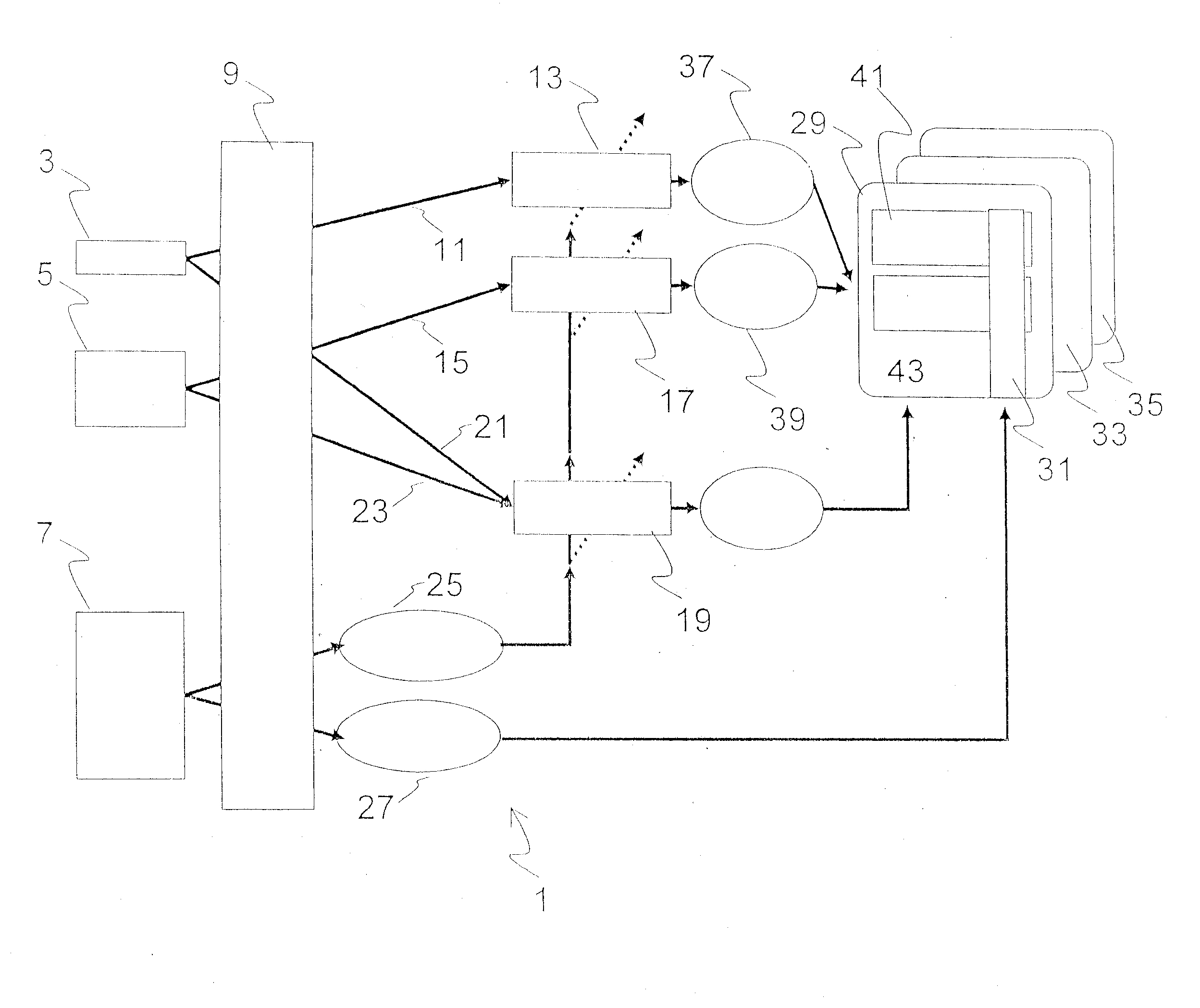
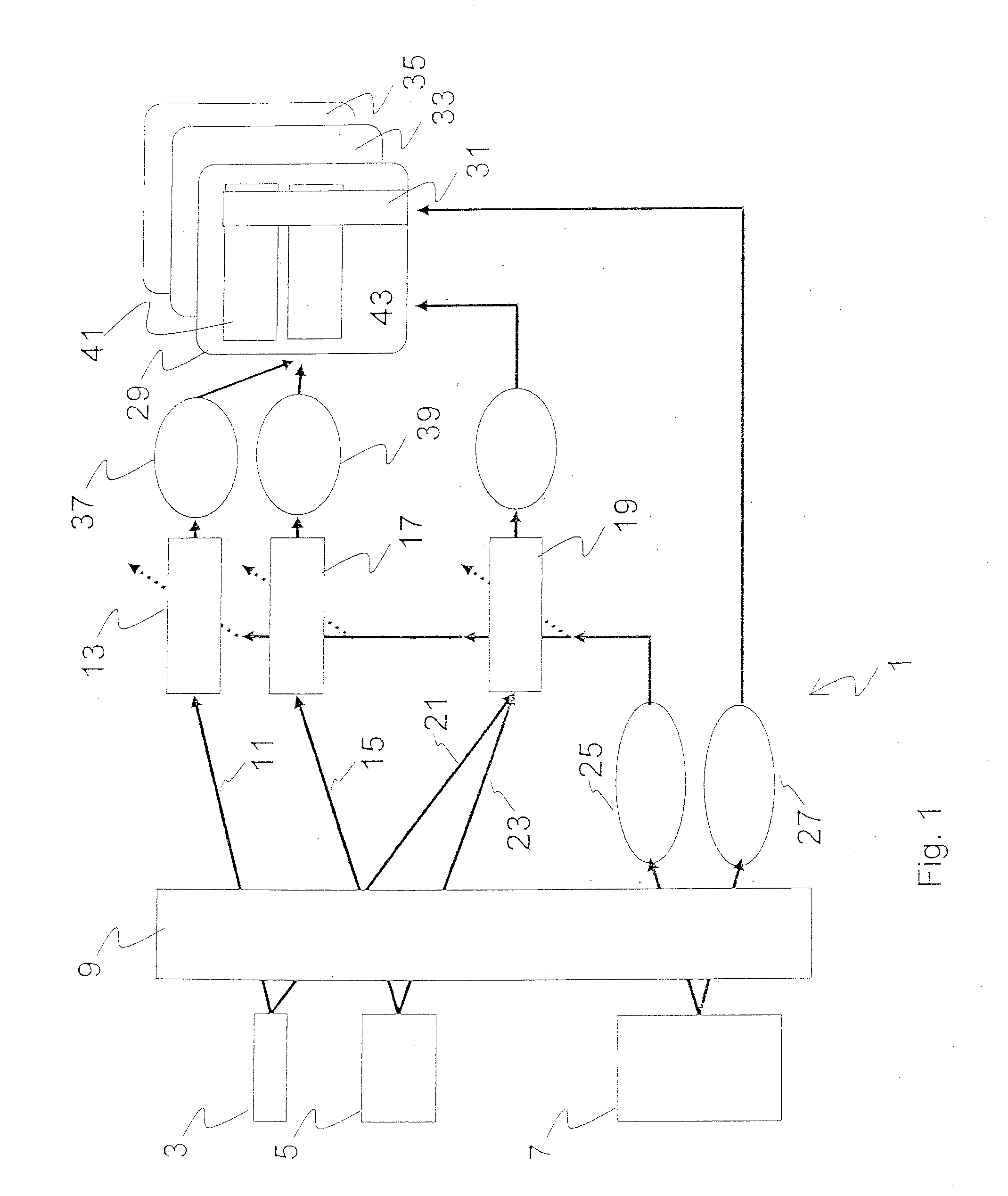
[0034]Referring to the drawings in particular, FIG. 1 schematically shows, in a simplified form, a device according to the present invention for monitoring a patient. This device 1 designed, for example, as an anesthesia apparatus, and the present invention is not limited to a device for monitoring anesthesia. The device 1 has two intravenous pumps 3 and 5 for two anesthetics, and at least one of the pumps 3 and 5 may also be equipped as a means for administering a volatile anesthetic for intravenous administration. The device 1 has, furthermore, an interface 7, by means of which inputs can be made via a keyboard, mouse or the like, not shown. The device 1 has, furthermore, an information management system 9, by means of which a connection can be established between the anesthesia apparatus, a hospital information system, a network or the like for providing data that are relevant in the individual case. Data from the intravenous pumps 3, 5 as well as from the interface 7 also flow i...


PUM


Abstract

A process for monitoring a patient by a monitoring device is provided in which simplified monitoring of the patient can be carried out on the basis of a suitable selection of the parameter values and / or ranges displayed in a special manner. A suitable device (1) is provided for carrying out the process.

Description

CROSS REFERENCE TO RELATED APPLICATIONS[0001]This application claims the benefit of priority under 35 U.S.C. § 119 of German Patent Application DE 10 2006 053 856.0 filed Nov. 14, 2006, the entire contents of which are incorporated herein by reference.FIELD OF THE INVENTION[0002]The present invention pertains to a process for monitoring at least one parameter of a patient with the use of a monitoring means, which has at least one display means for the simultaneous display of a plurality of parameter values at different points in time, as well as to a device with a display means for the simultaneous display of a plurality of parameter values at different points in time.BACKGROUND OF THE INVENTION[0003]The use of monitoring means, by means of which one or more parameters of the patient are monitored, is common in the modern care for and treatment of patients, the current technical possibilities permitting the determination of a plurality of measured values over time and the display th...

Claims


Application Information

Patent Timeline
IPC IPC(8): A61B5/00
CPCA61B5/0002A61B5/4821G06F19/3481A61M2202/0241G06F19/3418A61M5/142G16H20/17G16H40/67
Inventor HAAR, MARALBUSCHKE, WILFRIEDFRANZ, FRANKKUCK, KAIMEYER, JORG-UWESTAHLKOPF, SUSANNEWILKENING, MICHAELBOUILLON, THOMASSCHUMACHER, PETERSTETZER, BELA
Owner DRAGERWERK AG
Learn More