
Fluidics cassette for ocular surgical system

a technology of ocular surgery and fluidics, which is applied in the field of fluidics cassette for ocular surgery system, can solve the problems of significant tissue damage, excessive pressure within the eye may strain and injure the tissues of the eye, and the flow pressure is less accurately controlled

Active Publication Date: 2008-05-15
JOHNSON & JOHNSON SURGICAL VISION INC
View PDF38 Cites 100 Cited by
  • Summary
  • Abstract
  • Description
  • Claims
  • Application Information

AI Technical Summary

Benefits of technology

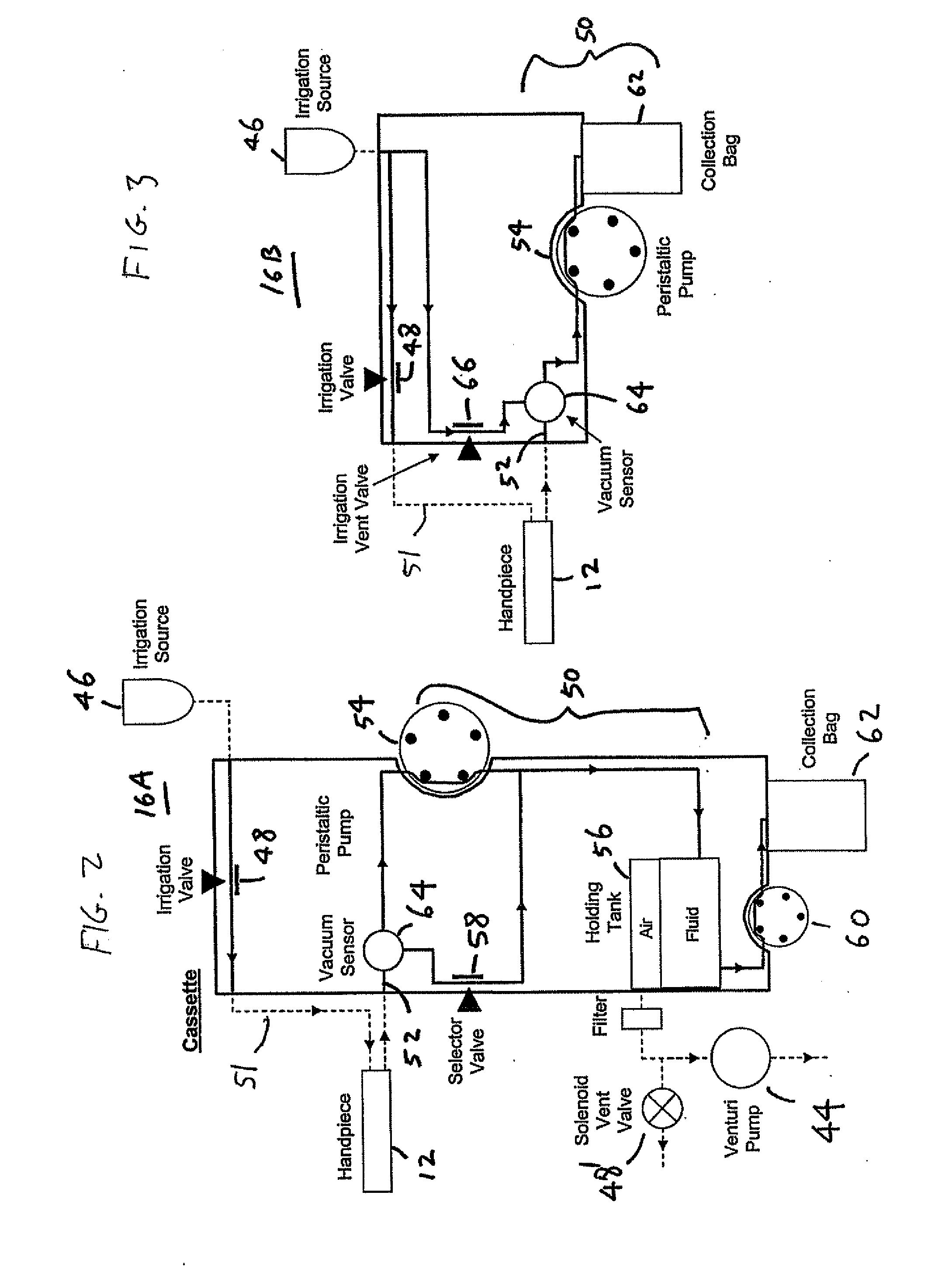
The present invention is about improving eye surgery by providing better methods, devices, and systems for eye treatment. The invention includes a console that can interchangeably accept multiple types of fluidic cassettes, which are used for eye surgery. The cassettes can be designed for displacement-based or vacuum-based aspiration modes, and may include visual indicators to identify their type. The invention also includes a vent valve that can vent the handpiece during operation. The invention provides greater flexibility and functionality for eye surgery procedures, making them safer and more effective.

Problems solved by technology

If the total volume of fluid in the eye is allowed to get too low at any time during the procedure, the eye may collapse and cause significant tissue damage.
Similarly, excessive pressure within the eye may strain and injure tissues of the eye.
The pressure of the flow, however, is less accurately controlled and the variations in vacuum may result in the feel or traction of the handpiece varying during a procedure.
Peristaltic and other displacement pump systems may also be somewhat slow.
However, Venturi pumps, rotary vane pumps, and other vacuum-based aspiration flow systems are subject to pressure surges during occlusion of the treatment probe, and such pressure surges may decrease the surgeon's control over the eye treatment procedure.

Method used


Image

  • Fluidics cassette for ocular surgical system
  • Fluidics cassette for ocular surgical system
  • Fluidics cassette for ocular surgical system

Examples


Embodiment Construction

[0038]The present invention generally provides improved devices, systems, and methods for treating an eye of the patient.

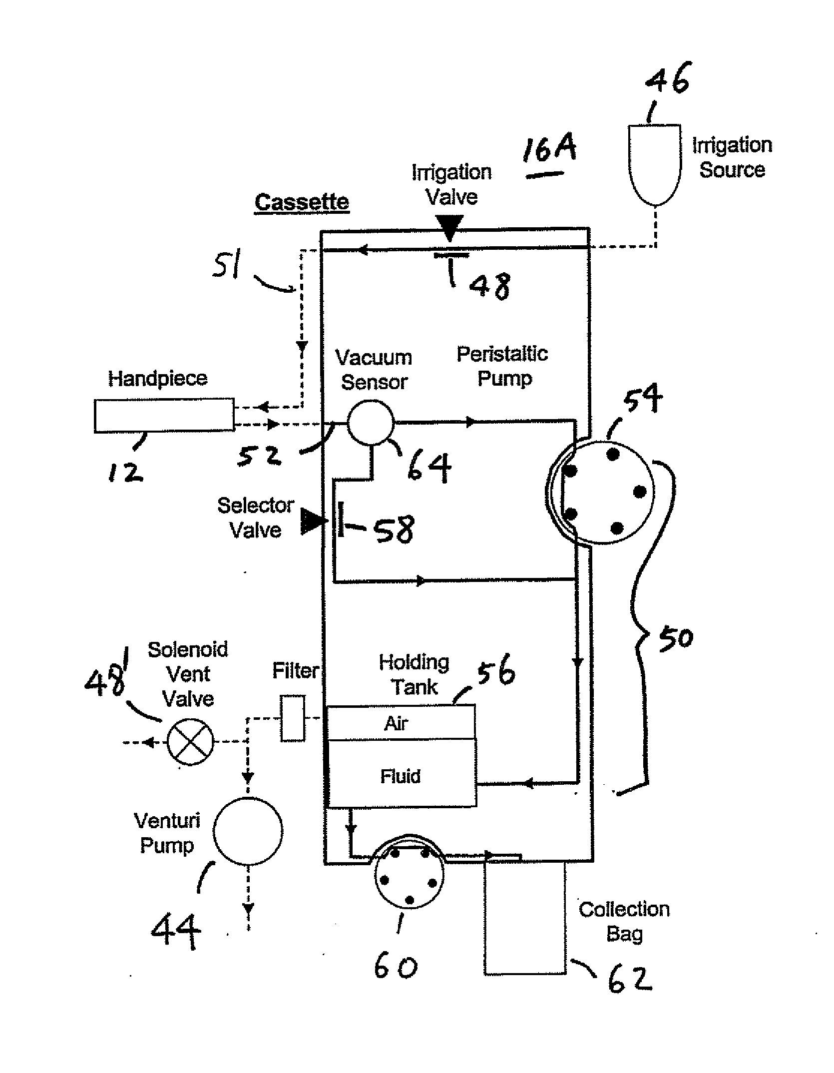
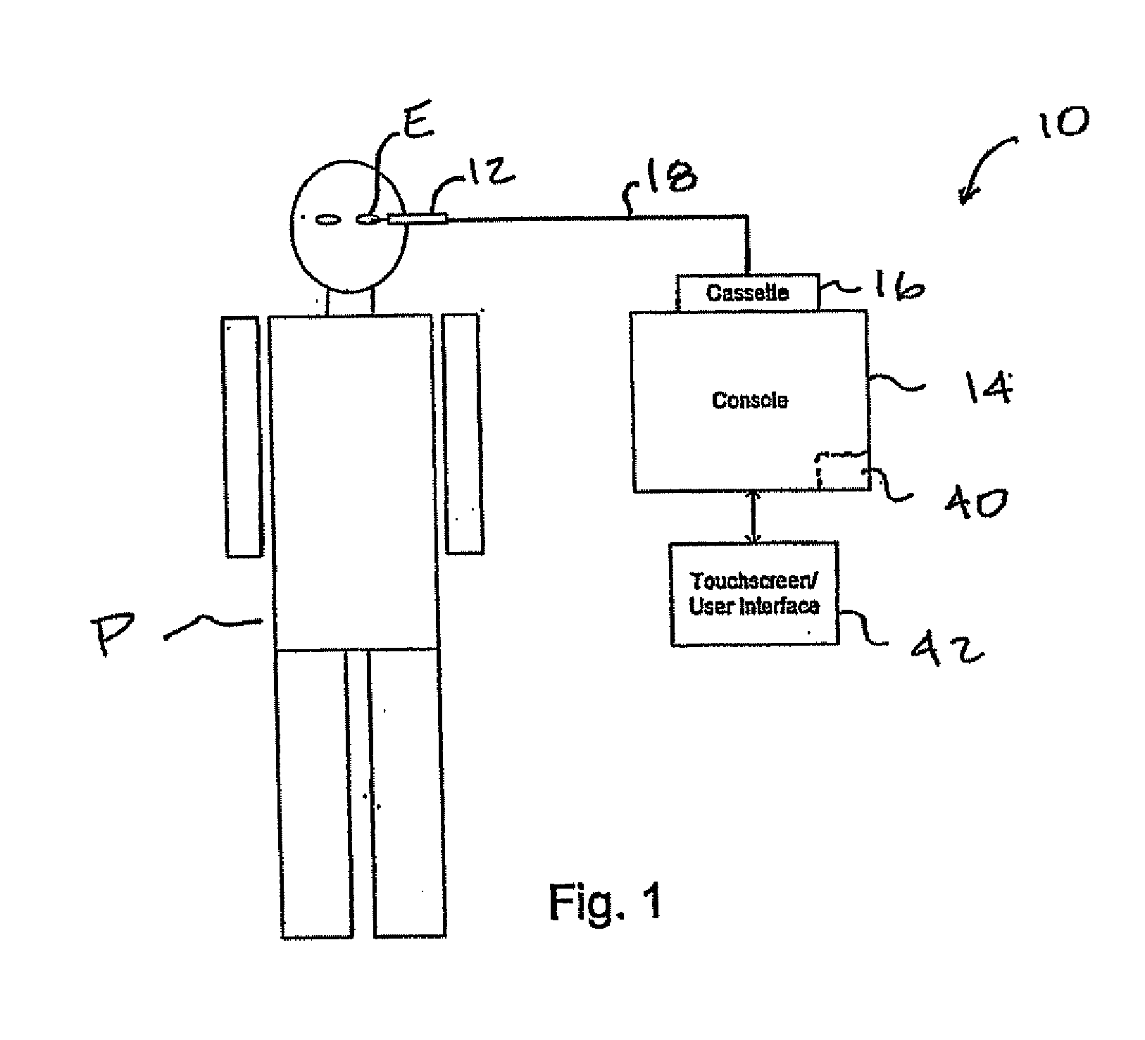
[0039]In one embodiment of the present invention, a fluid aspiration system includes a console on which multiple types of interchangeable fluidic cassettes can be mounted. Each type of cassette may include components for enabling one or both of displacement-based and vacuum-based aspiration. The cassette may include a surgical fluid network, and mounting of the cassette to the console allows various network elements of the cassette to interface with corresponding components of the console. The fluid network of the cassette may include resiliently deformable tubing, a pressure sensor, a holding tank or chamber, and the like. The components of the fluid network may change depending on whether the cassette enables displacement-based or vacuum-based aspiration, or both. For example, in order to enable displacement-based aspiration, a cassette body may constrain a segm...


PUM


Abstract

An eye treatment cassette includes a handpiece, a vacuum source, a holding tank, a collection bag, and a displacement-based pump. The handpiece is configured to aspirate fluids from a patient's eye. The vacuum source communicates with the handpiece. The holding tank is interposed between the handpiece and the vacuum source, and is configured to hold the aspirated fluids. The collection bag is connected to the holding tank for collecting the aspirated fluids. The pump is coupled to the holding tank and is configured to operate while the vacuum source continues to aspirate fluids via the handpiece to drain the aspirated fluids from the holding tank.

Description

RELATED APPLICATION[0001]The present application claims priority under 35 U.S.C § 119(e) to provisional application No. 60 / 865,161, filed on Nov. 9, 2006 under the same title. Full Paris Convention priority is hereby expressly reserved.BACKGROUND OF THE INVENTION[0002]The present invention is generally related to methods, devices, and systems for controlling surgical fluid flows, particularly during treatment of an eye.[0003]The optical elements of the eye include both a cornea (at the front of the eye) and a lens within the eye. The lens and cornea work together to focus light onto the retina at the back of the eye. The lens also changes in shape, adjusting the focus of the eye to vary between viewing near objects and far objects. The lens is found just behind the pupil, and within a capsular bag. This capsular bag is a thin, relatively delicate structure which separates the eye into anterior and posterior chambers.[0004]With age, clouding of the lens or cataracts are fairly common...

Claims


Application Information

Patent Timeline
Patent Type & Authority Applications(United States)
IPC IPC(8): A61M1/00A61M37/00
CPCA61F9/00745A61M1/0058A61M2205/123A61M2210/0612A61M2205/505A61M2205/52A61M2205/3331A61M1/77A61M3/0201A61M1/72
Inventor MURI, JOHN I.EDWARDS, CRAIG
Owner JOHNSON & JOHNSON SURGICAL VISION INC
Learn More