
Curved focal plane receiver for concentrating light in a photovoltaic system

a photovoltaic system and receiver technology, applied in the direction of photovoltaics, electrical equipment, semiconductor devices, etc., can solve the problems of large potential differences within the solar cell, difficult to achieve uniform high-intensity illumination on the flat focal plane of the receiver, and high optics requirements

Inactive Publication Date: 2008-05-22
THE BOEING CO
View PDF11 Cites 166 Cited by
  • Summary
  • Abstract
  • Description
  • Claims
  • Application Information

AI Technical Summary

Problems solved by technology

Achieving uniform high-intensity illumination on a flat focal plane of a receiver is difficult and requires high precision optics.
These types of power densities can deliver very high system efficiencies, but also can create large potential differences within a solar cell and between solar cells connected in a circuit.
If the illumination is not uniform, differences in current output develops in the solar cells.
These differences may lead to resistive power loss and unpredictable electric fields within the solar cells, causing degradation and leading to a solar cell failure.
As a result, the effective illumination is often reduced.
With such off-angle illumination, slight deviations in the optical path of the concentrated illumination beam can cause portions of the beam to miss the cell receiver area.
These deviations may be caused by tracking errors, imperfections in the optics, deformation of the optics due to thermal expansion, or wind loading, or the like.
This type of element, however, contributes to optical losses and adds to the cost of a concentrating photovoltaic system.
Thus, creating concentrating photovoltaic systems at a reasonable cost to produce energy is difficult.

Method used


Image

  • Curved focal plane receiver for concentrating light in a photovoltaic system
  • Curved focal plane receiver for concentrating light in a photovoltaic system
  • Curved focal plane receiver for concentrating light in a photovoltaic system

Examples


Embodiment Construction

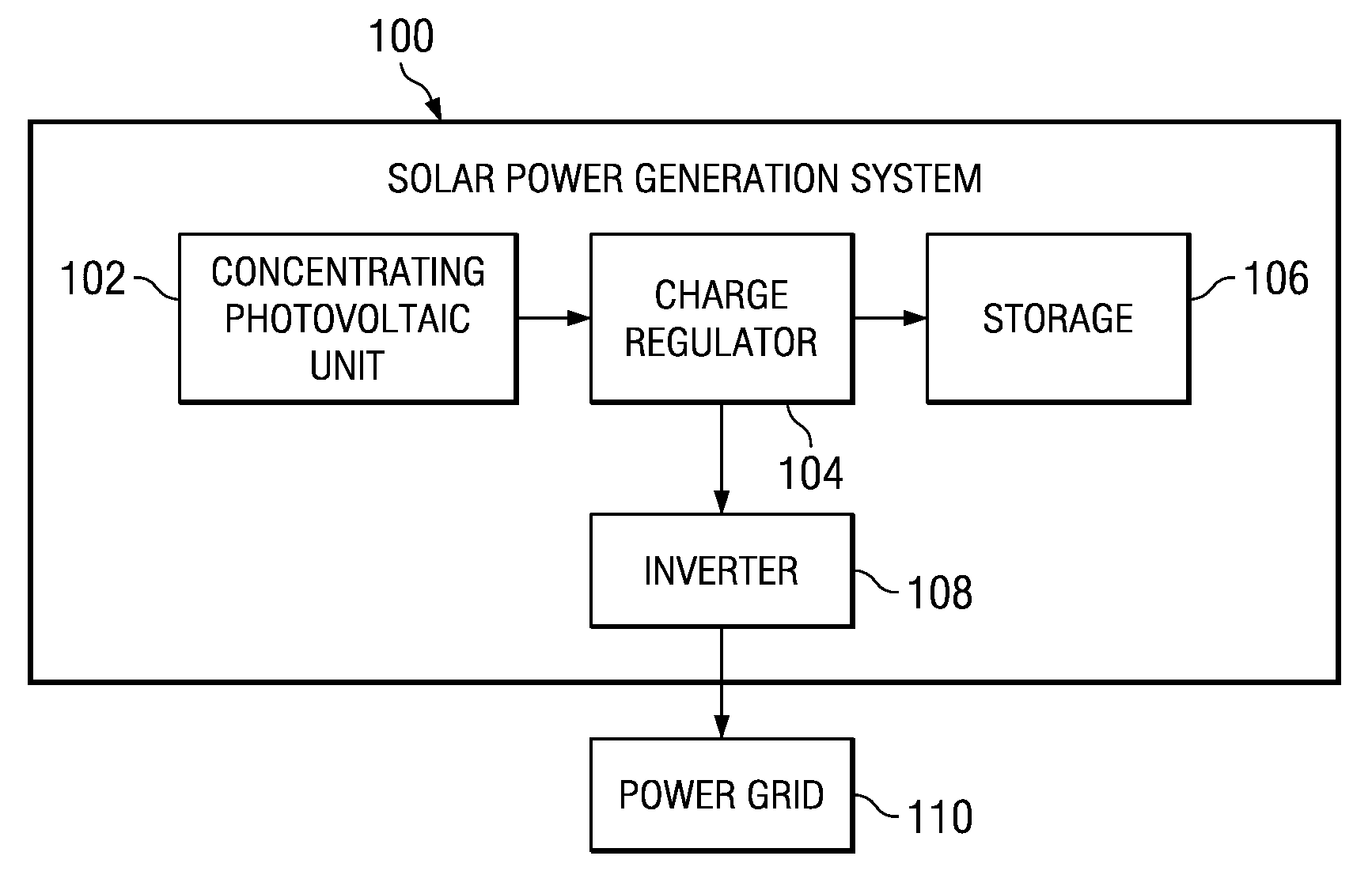
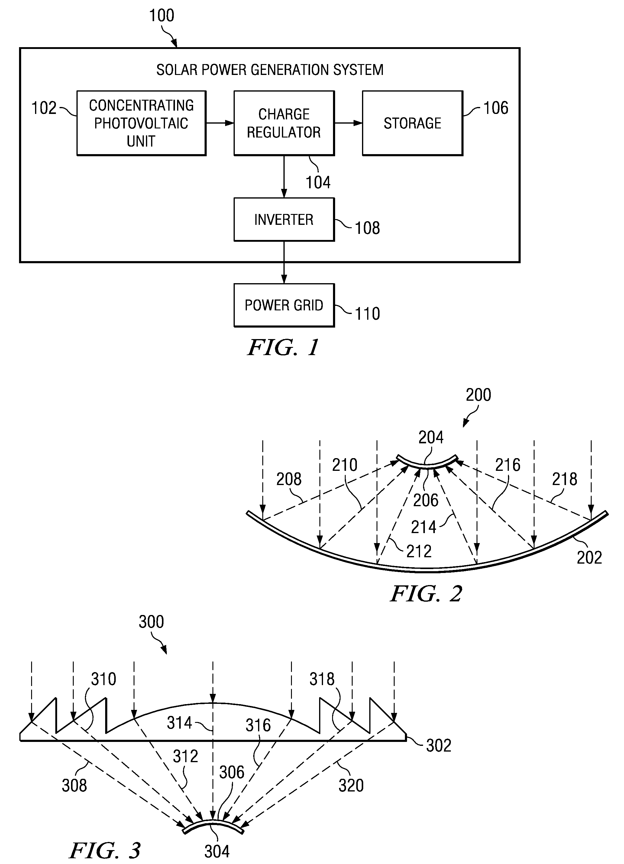
[0027]With reference now to the figures and in particular with reference to FIG. 1, a diagram illustrating a solar-powered generation system is depicted in accordance with an advantageous embodiment of the present invention. Solar-powered generation system 100 is an example of a solar-powered generation system in which different embodiments of the present invention may be implemented.

[0028]Solar-powered generation system 100 includes a concentrating photovoltaic unit 102, charge regulator 104, storage 106, and inverter 108. Concentrating photovoltaic unit 102 contains concentrating optics with a receiver area containing one or more solar cells to generate energy from sunlight. Charge regulator 104 is used to direct electricity generated by concentrating photovoltaic unit 102 to storage 106 or to inverter 108. Charge regulator 104 ensures that batteries in storage 106 are charged and protects those batteries from discharging. Storage 106 is an optional component for these examples. I...


PUM


Abstract

An apparatus having a concentrating optic member, wherein the concentrating optic member redirects light to form concentrated illumination. The apparatus also has a structure with a curved surface positioned to receive the redirected light and a set of solar cells connected to a curved surface of the structure, wherein the curved surface is curved such that all of the set of solar cells receive the redirected light at substantially the same intensity.

Description

BACKGROUND INFORMATION[0001]1. Field of Invention[0002]The present invention relates to a method and apparatus for generating energy using solar cells. More particularly, the present invention relates to a method and apparatus for generating energy using solar cells in a concentrating photovoltaic system.[0003]2. Background Description[0004]One type of solar energy involves the use of solar cells to generate electricity. This type of solar power technology is also referred to as photovoltaics. The solar cells used are semiconductor devices that convert photons into electricity. Individual solar cells may be grouped together to form modules, which in turn, may be arranged into groupings called solar arrays. Concentrating photovoltaics are widely regarded as a key in making solar energy cost competitive with respect to other energy sources, such as fossil fuels.[0005]With concentrating photovoltaics, sunlight is collected from a large area and concentrated on a relatively small receiv...

Claims


Application Information

Patent Timeline
IPC IPC(8): H01L31/00
CPCH01L31/035281Y02E10/52H01L31/0547H01L31/0543Y02E10/549
Inventor KINSEY, GEOFFREY S.
Owner THE BOEING CO
Learn More