
Movable partitions with lateral restraint devices and related methods

a technology of lateral restraint device and moving partition, which is applied in the field of moving partitions, can solve the problems of lateral displacement of the lower edge of the door, smoke and flames may intrude around the door, and the door seal may be broken

Active Publication Date: 2008-05-22
WOW DOOR CORP
View PDF66 Cites 43 Cited by
  • Summary
  • Abstract
  • Description
  • Claims
  • Application Information

AI Technical Summary

Benefits of technology

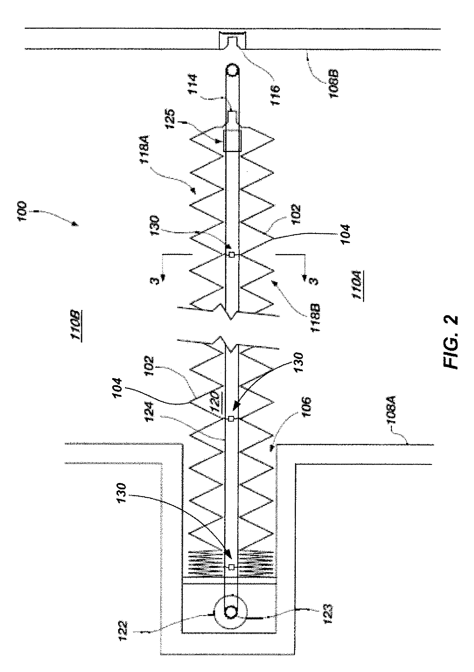
[0010]In accordance with another embodiment of the present invention, a method of restraining lateral movement of a movable partition is provided. The method includes suspending a first structure from a support structure, wherein the first structure includes a first plurality of panels wherein each panel is hingedly coupled to adjacent panel. A second structure is also supported from the support structure at a laterally spaced location relative to the first structure, the second structure including a second plurality of hingedly coupled panels. At least one elongated member is supported from the support structure along an axis extending away from the support structure and between the first structure and the second structure. The elongated member is substantially restrained from being laterally displaced toward either the first structure or the second structure.
[0011]In accordance with yet another embodiment, a device for preventing lateral displacement of one or more structures in a moveable partition is provided. The device includes a trolley and an elongated member coupled with and extending from the trolley. The trolley includes a structural member and a first plurality of roller elements coupled with the structural member on a first side thereof. At least two roller elements of the first plurality have rotational axes lying in a first plane and at least one roller element of the first plurality has a rotational axis lying outside of the first plane. A second plurality of roller elements is coupled with the structural member on a second side thereof. At least two roller elements of the second plurality having rotational axes lying in the first plane and at least one roller element of the second plurality has a rotational axis lying outside of the first plane. The trolley further includes a third plurality of roller elements coupled with the structural member. The rotational axes of each of the third plurality of roller elements are angularly displaced relative to the rotational axes of each of the first plurality of roller elements.

Problems solved by technology

However, even when a moveable partition is properly closed, the door seal may be broken, for example, if the lower edge of the door is laterally displaced relative to the top edge of the door.
Such lateral displacement of the lower edge of the door can be caused, for example, by a draft created by a fire, an improperly balanced HVAC system, or simply by a person pushing on the door.
When the seal is broken, smoke and flames may intrude around the door if the door is being used as a fire barrier.
At a minimum, displacement of the base of the door is unsightly and significantly reduces the door's effectiveness as a privacy screen and noise barrier.
However, the use of a track can present various issues.
For example, a track disposed in the floor can pose a safety issue, regardless of whether it protrudes above the floor or is recessed within the floor, potentially resulting in a person twisting an ankle or tripping and falling.
Likewise, such a track may act as a significant obstacle for wheeled conveyances.
Additionally, such a guide track, being exposed when the associated door is in a retracted state, is prone to damage and may act as a collection point for dirt and debris.

Method used


Image

  • Movable partitions with lateral restraint devices and related methods
  • Movable partitions with lateral restraint devices and related methods
  • Movable partitions with lateral restraint devices and related methods

Examples


Embodiment Construction

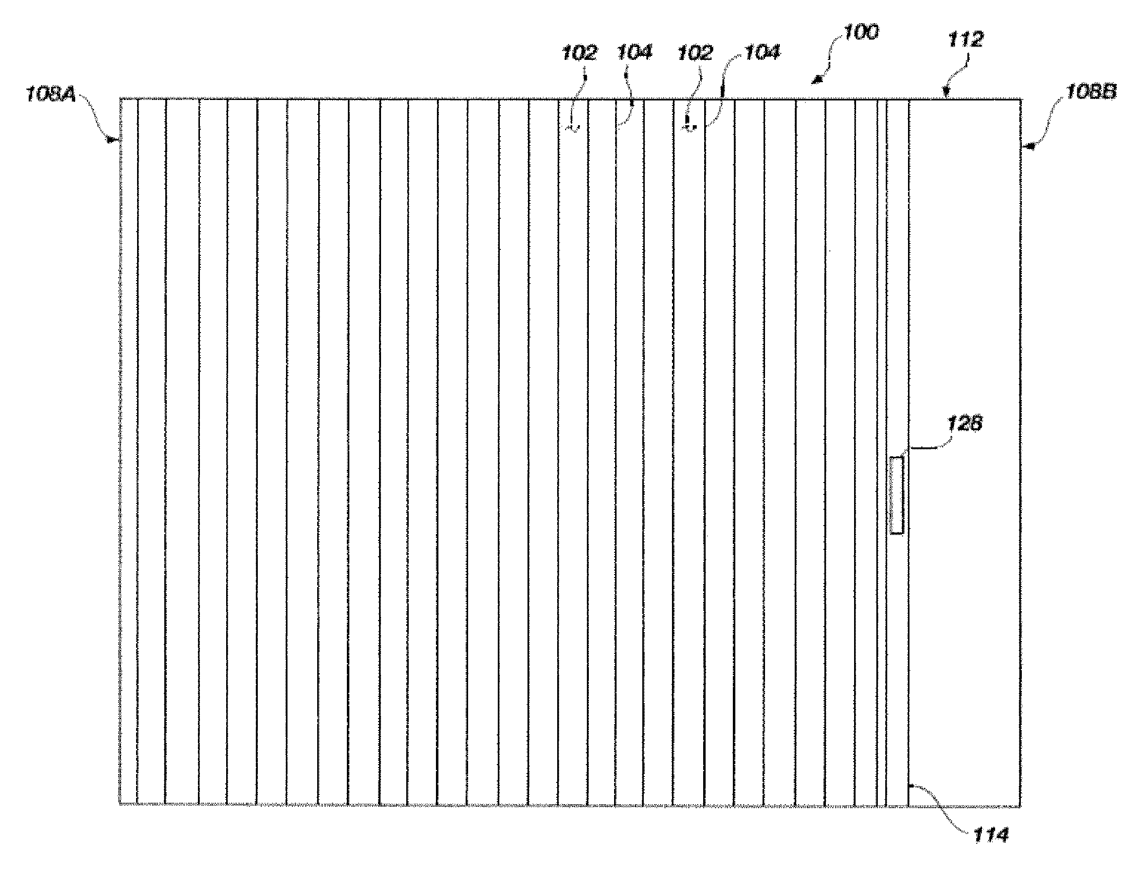
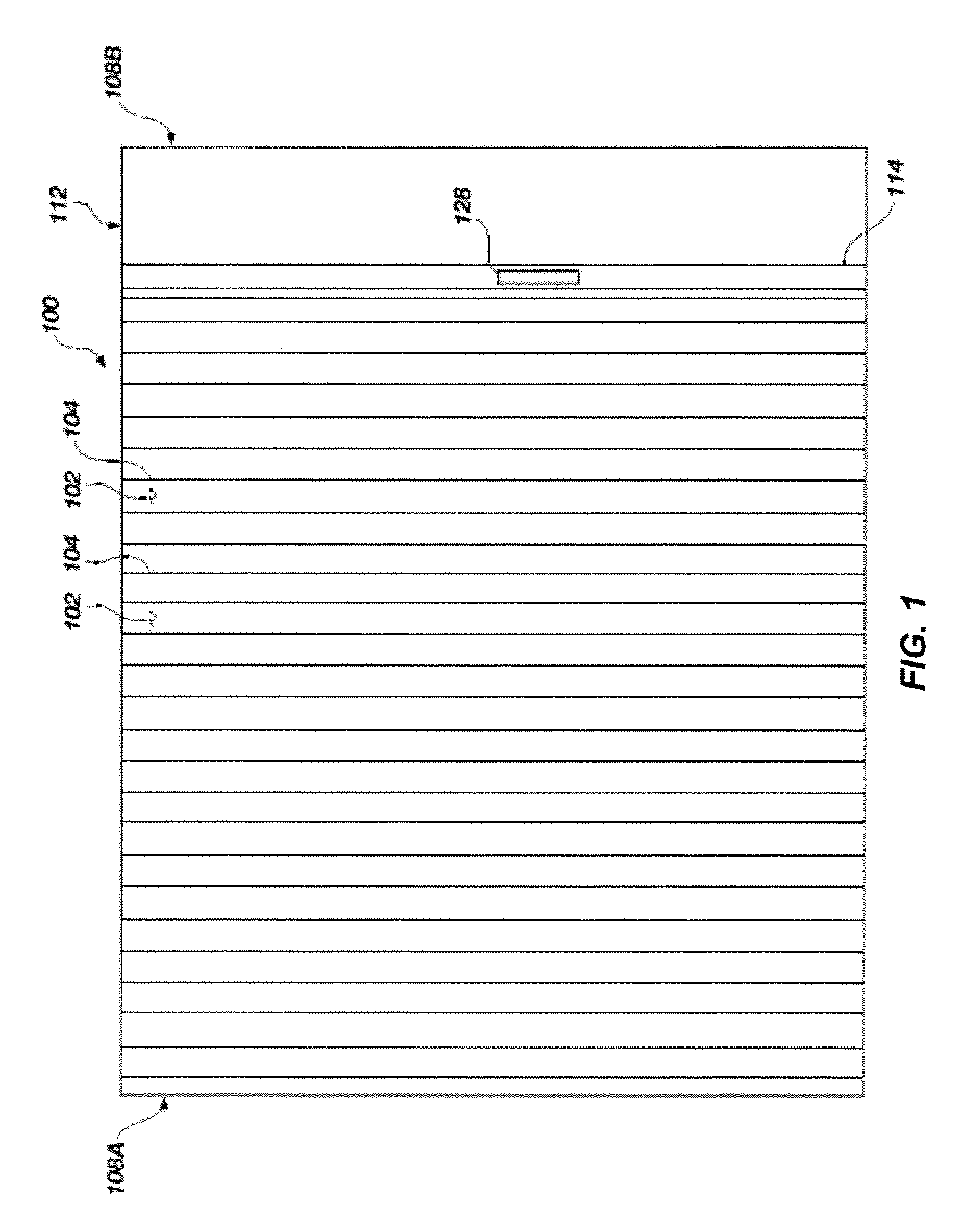
[0020]Referring to FIGS. 1 and 2, an elevation view and a plan view are shown, respectively, of a moveable partition 100. In the example shown in FIGS. 1 and 2, the partition 100 may be in the form of folding door. In certain embodiments, the partition 100 may be used, for example, as a security door, a fire barrier or as both. In other embodiments, the partition need not be utilized as a fire or security barrier, but may be used, for example, to subdivide a larger space into smaller rooms or areas or it may be used as a sound barrier.

[0021]The partition 100 may be formed with a plurality of panels 102 that are connected to one another with hinges 104 or other hinge-like structures in an alternating pattern of panel 102 and hinge 104. The hinged connection of the individual panels 102 enables the panels to fold relative to each other in an accordion or a plicated manner such that the partition 100 may he compactly stored, such as in a pocket 106 formed in a wall 108A of a building w...


PUM

PropertyMeasurementUnit
lengthaaaaaaaaaa
forceaaaaaaaaaa
structureaaaaaaaaaa

Abstract

Embodiments of the present invention include movable partitions and devices, methods and systems that help to limit or prevent lateral displacement of movable partitions. In accordance with one embodiment of the present invention, a movable partition includes two structures, each structure having a first plurality of panels, and each panel being hingedly coupled to an adjacent panel. The two panels are each supported from an overhead track at laterally spaced locations. One or more lateral restraint devices are supported from the overhead track at a location between the two laterally spaced structures. The lateral restraint device may include a trolley disposed in a channel of the overhead track and an elongated member coupled with the trolley and extending away from the trolley to a location proximate a lower edge of the first structure and a lower edge of the second structure.

Description

CROSS-REFERENCE TO RELATED APPLICATIONS[0001]This application is a continuation-in-part of U.S. patent application Ser. No. 11 / 796,325 entitled METHOD, APPARATUS AND SYSTEM FOR CONTROLLING A MOVABLE PARTITION filed on Apr. 27, 2007 and is a continuation-in-part of U.S. patent application Ser. No. 11 / 934,566 entitled MOVABLE PARTITIONS WITH LATERAL RESTRAINT DEVICES AND RELATED METHODS filed on Nov. 2, 2007 and which claims priority of U.S. Provisional Application No. 60 / 856,597 entitled MOVABLE PARTITIONS WITH LATERAL RESTRAINT DEVICES AND RELATED METHODS filed on Nov. 3, 2006, the disclosures of each of which are incorporated by reference herein in their entireties.TECHNICAL FIELD[0002]The present invention relates to moveable partitions and, more particularly, to systems, apparatuses and methods for preventing lateral displacement of one or more portions of such partitions.BACKGROUND[0003]Moveable partitions are utilized in numerous situations and environments for a variety of pur...

Claims


Application Information

Patent Timeline
Patent Type & Authority Applications(United States)
IPC IPC(8): E05D15/26
CPCE06B3/48E05Y2900/132E05D15/063Y10T29/49826E05D15/08E05D15/26Y10T16/381E06B3/94E05D15/0652Y10T292/388
Inventor GOODMAN, E. CARL
Owner WOW DOOR CORP
Learn More