
Seat belt apparatus

Active Publication Date: 2008-05-22
AUTOLIV DEV AB
View PDF6 Cites 2 Cited by
  • Summary
  • Abstract
  • Description
  • Claims
  • Application Information

AI Technical Summary

Benefits of technology

[0007] In at least one embodiment of the present invention, the object is to provide a highly reliable seat belt apparatus which can reduce the extent of deviation in retracting the seat belt webbing when the switch is shifted or between when the seat belt webbing is retracted and when the webbing is pulled out and which can prevent the unintentional interference between the projecting portions when the seat webbing is pulled out or retracted.
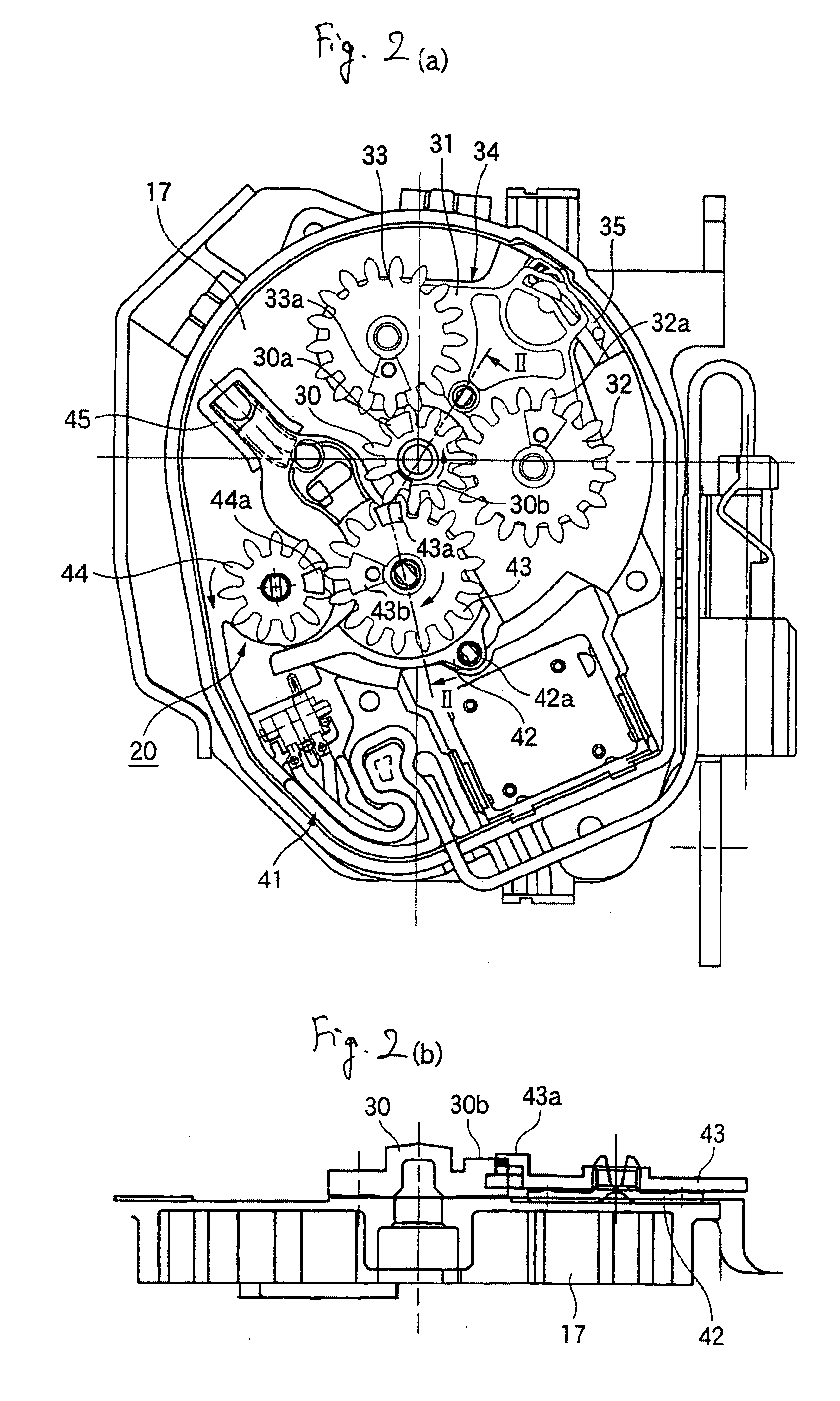
[0013] In at least one embodiment of the present invention, the first projecting portion and the second projecting portion are provided on the side of the drive gear and the side of the first gear, respectively, which are capable of being brought into abutment with each other so that the switch lever is shifted from the first position to the second position. The third projecting portion and the fourth projecting portion are provided on the side of the first gear and the side of the second gear, respectively, which are capable of being brought into abutment with each other so that the switch lever is shifted from the second position to the first position. The abutment position between the first and second projecting portions and the abutment position between the third and fourth projecting portions differ from each other in the axial direction of the spindle. This configuration may provide a highly reliable seat belt apparatus which can reduce the extent of deviation in retracting the seat belt webbing when the switch is shifted or between when the webbing is retracted and when the webbing is pulled out and which can prevent the unintentional interference between the projecting portions when the webbing is pulled out or retracted.

Problems solved by technology

In this case, however, there may be a possibility that the projecting portions interfere with each other unintentionally at a certain number of revolutions.

Method used


Image

  • Seat belt apparatus
  • Seat belt apparatus
  • Seat belt apparatus

Examples


Embodiment Construction

[0023] Hereinafter, a seat belt apparatus according to an embodiment of the invention will be described in detail by reference to the drawings.

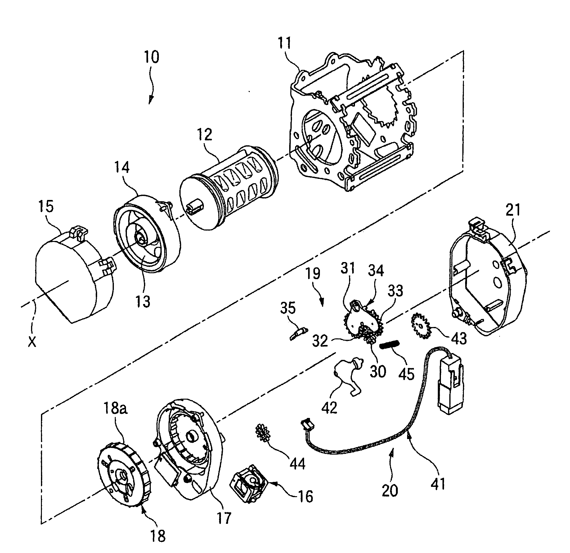
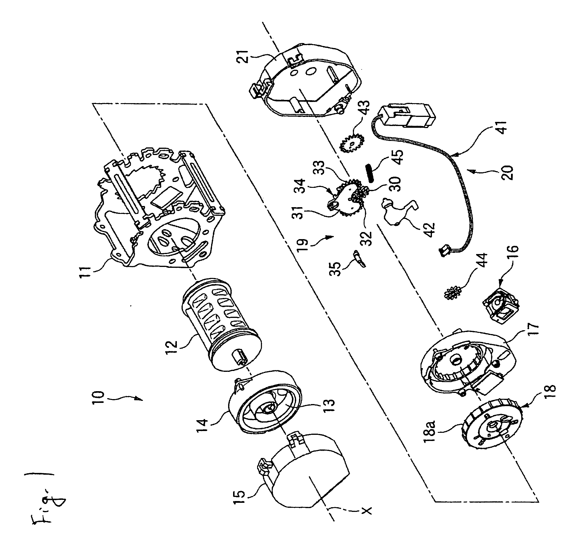
[0024] A seat belt retractor 10, which is a seat belt apparatus according to an embodiment of the invention, includes, as shown in FIG. 1, a retractor frame 11, and a spindle 12 for winding thereround webbing (not shown) is supported rotatably in the retractor frame 11.

[0025] A retractor spring 13 for biasing the spindle 12 in a seat belt winding direction is attached to the retractor frame 11 by a holder 14 and a cover 15 at one axial end side of the spindle.

[0026] Provided at the other axial end side of the spindle 12 are an acceleration sensor 16, which is provided in such a manner as to be tilted about a horizontal axis within the seat belt retractor 10 for detecting a horizontal acceleration of a vehicle, an inertia element assembly 18, which is disposed within a bearing plate 17 for locking a pull-out operation of a seat belt accordi...


PUM


Abstract

In a seat belt apparatus, a first projecting portion and a second projecting portion which are capable of being brought into abutment with each other so that a switch lever is shifted from a switch OFF position to a switch ON position are provided on a side of a drive gear and a side of a first gear, respectively. A third projecting portion and a fourth projecting portion, which are capable of being brought into abutment with each other so that the switch lever is shifted from the switch ON position to the switch OFF position, are provided on the side of the first gear and a side of a second gear. An abutment position between the first and second projecting portions and an abutment position between the third and fourth projecting portions differ from each other in an axial direction of a spindle.

Description

CROSS REFERENCE TO RELATED APPLICATIONS [0001] This application claims priority to JP 2005-206053, filed Jul. 14, 2005 and PCT / JP2006 / 31105, filed Jun. 1, 2006. FIELD OF INVENTION [0002] The present invention relates to a seat belt apparatus, and more particularly to a seat belt apparatus which can detect when a seat belt is being worn by an occupant of a vehicle, otherwise referred to as a wearing state. BACKGROUND OF THE INVENTION [0003] In a conventional seat belt apparatus, there is known a construction in which a remainder switch for outputting an ON / OFF signal for detecting a wearing or non-wearing state of a seat belt is disposed inside of a seat belt retractor mounted in a vehicle. A wearing state of the seat belt occurs when the seat belt is worn by an occupant of the vehicle so as to securely position and restrain the occupant within a seat of the vehicle. [0004] In the seat belt apparatus, three gears, which are linked with the rotation of a spindle, are provided, and pro...

Claims


Application Information

Patent Timeline
IPC IPC(8): H01H19/00
CPCB60R22/405B60R2022/4825B60R22/48F16H1/20B60R2022/4808
Inventor SAITO, KENTAROUHIBATA, GANTA
Owner AUTOLIV DEV AB
Learn More