Magnetically-damped supercritical transmissions

Inactive Publication Date: 2008-05-22
EUROCOPTER
View PDF9 Cites 16 Cited by
  • Summary
  • Abstract
  • Description
  • Claims
  • Application Information

AI Technical Summary

Benefits of technology

[0016]the mechanical device may include a return member conferring greater mechanical stiffness to the damper;

Problems solved by technology

As a result in particular of the complexity and the critical nature of the hardware and software components of an active magnetic bearing, implementing them on board a rotorcraft suffers from the high development costs that are necessary in order to enable them to be qualified or certified.
The mass and the stability of such a system make it difficult to use for supporting a rotorcraft transmission shaft.

Method used


Image

  • Magnetically-damped supercritical transmissions
  • Magnetically-damped supercritical transmissions
  • Magnetically-damped supercritical transmissions

Examples


Embodiment Construction

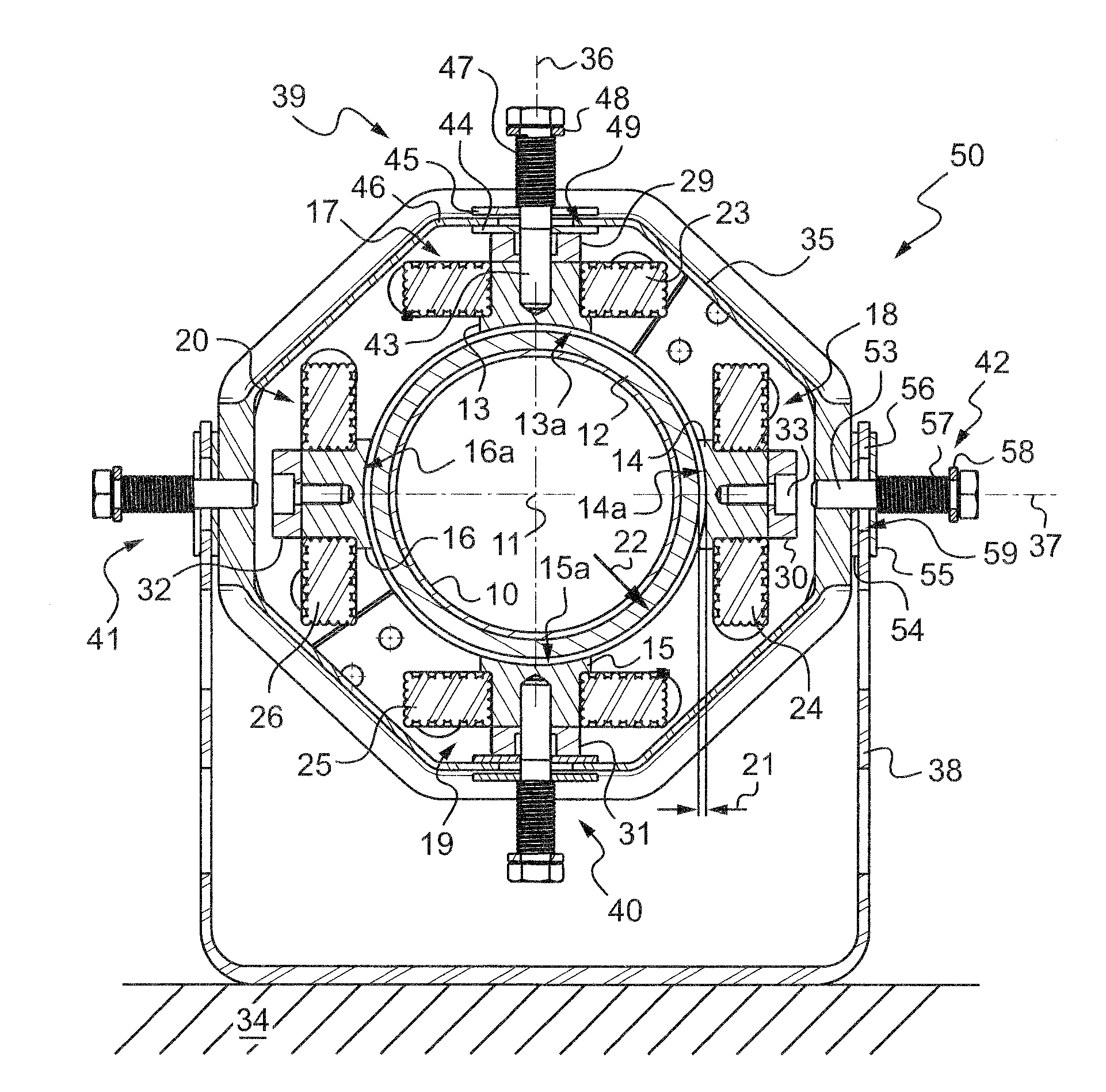
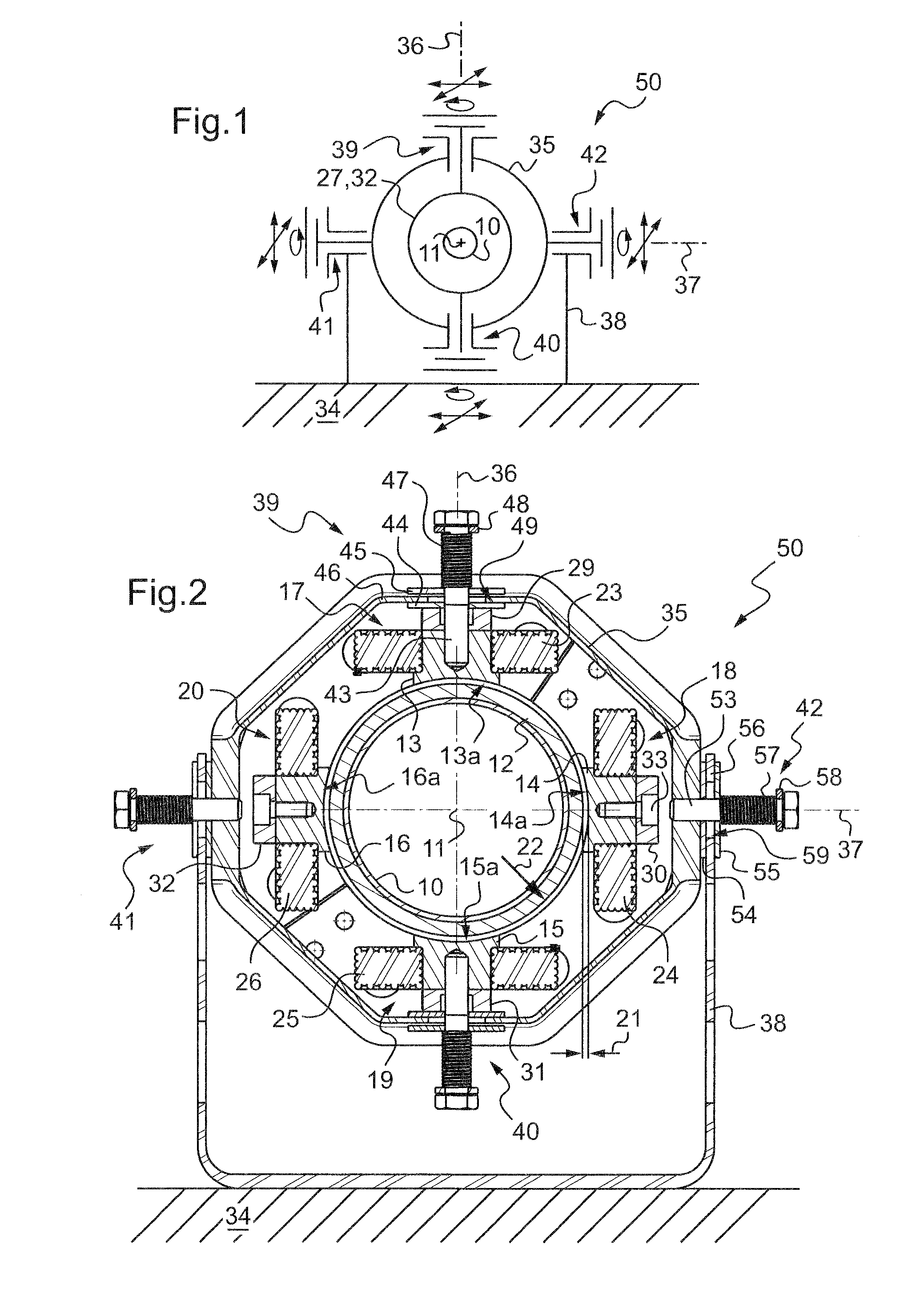
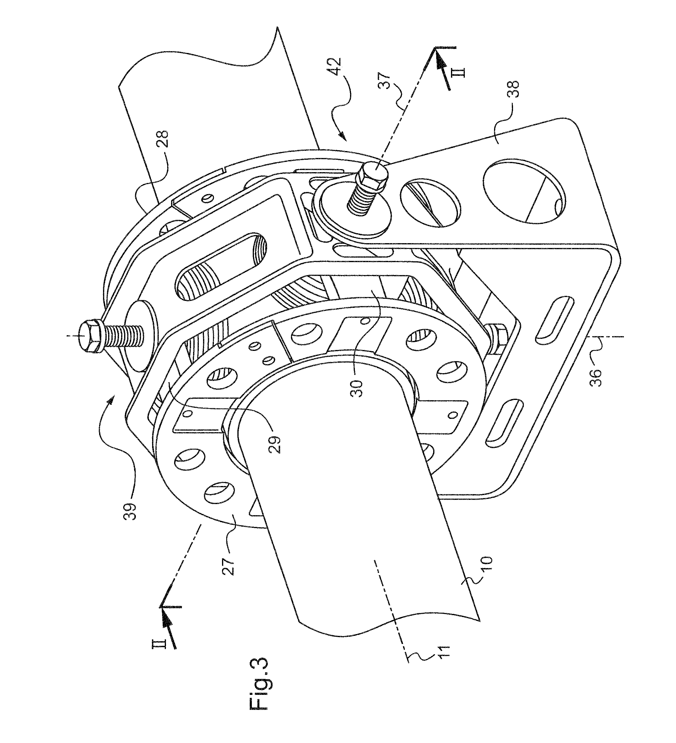
[0028]With reference to FIGS. 2 to 4 in particular, the hollow transmission shaft 10 extends along an axis 11 and presents on its outside face a projecting ring 12 of ferromagnetic material selected to co-operate with (i.e. to be attracted by) the cores 13 to 16 of each of electromagnets 17 to 20 of the magnetic damper.

[0029]The function of the magnetic damper is to limit the radial movement speeds of the portion of the shaft around which it extends, and where appropriate to hold the shaft in a position that is substantially centered relative to the end faces 13a to 16a of the four cores 13 to 16, i.e. with substantially identical airgaps 21 for all four electromagnets.

[0030]By way of example, for a shaft having a diameter of about 100 mm, an airgap of about 1 mm or 2 mm is provided when the shaft is centered.

[0031]The four electromagnets are identical and rigidly interconnected.

[0032]The respective inside faces 13a to 16a of the cores 13 to 16 are of concave cylindrical shape of ra...


PUM


Abstract

The invention relates to a mechanical transmission system for a rotorcraft, the system including a supercritical transmission shaft (10) and an active magnetic damper (17 to 20) secured to the structure (34) of the aircraft via a mechanical damper (50).

Description

[0001]The present invention relates to improvements applied to systems for transmitting mechanical power by means of a transmission shaft that is connected to a structure, in particular an aircraft structure, via an active magnetic bearing, or damper.[0002]The technical field of the invention is that of manufacturing helicopters.BACKGROUND OF THE INVENTION[0003]The present invention relates in particular to a transmission system comprising a transmission shaft presenting two longitudinal ends, in which a connection member, such as a deformable coupling member, is fitted to each end of the shaft, the two connection members connecting the shaft respectively to two rotary members of the rotorcraft such as a main gearbox (MGB) at one end and a tail rotor gearbox (TRG) at the other end, thus enabling the shaft to drive a rear rotor, or tail rotor, of the rotorcraft from the MGB via the TRG.[0004]Patents FR 2 817 234 and U.S. Pat. No. 6,680,554 describe such a power transmission system be...

Claims


Application Information

Patent Timeline
IPC IPC(8): B64D35/00
CPCF16C32/044Y10T464/50F16F15/06F16F15/03F16F15/10
Inventor MANFREDOTTI, THOMASSEQUERA, DAMIEN
Owner EUROCOPTER
Why Eureka
Try Eureka