Shutter device and image pickup apparatus

Inactive Publication Date: 2008-05-22
CANON KK
View PDF3 Cites 1 Cited by
  • Summary
  • Abstract
  • Description
  • Claims
  • Application Information

AI Technical Summary

Benefits of technology

[0025]The present invention has been made in consideration of the above situation, and provides a shutter device and an image pickup apparatus which can precisely measure a shutter open time.
[0026]According to the present invention, a shutter device includes a blade member and a detecting unit. The blade member includes a first blade, a second blade, and a detection portion. The blade member controls a time of exposure, performed on a recording medium, on the basis of a magnitude of a width of a slit. The slit includes slit portions and is provided when the first blade and the second blade travel. The detecting unit detects a state of the slit width. A cut-away portion is provided at the blade member so that a width of the slit portion at the detection portion of the blade member is wider than a width of the slit portion at a limiting portion of the blade member. The detection portion is detected by the detecting unit. The limiting portion limits the exposure time.

Problems solved by technology

Therefore, as in the shutter device discussed in the aforementioned document, there is a problem that, when an open time of shutter blades is detected by a detecting unit that makes use of a light-emitting diode and a photo-transistor, a difference is produced between an actual slit open time and the slit open time detected by the detecting unit.
Therefore, the shutter open time cannot be measured.
Even if, in the above-described condition, an attempt is made to correct the change in the shutter precision or to detect the closing of the blades, the correction of the change in the shutter precision and the detection of the closing of the blades cannot be performed precisely.

Method used


Image

  • Shutter device and image pickup apparatus
  • Shutter device and image pickup apparatus
  • Shutter device and image pickup apparatus

Examples


first exemplary embodiment

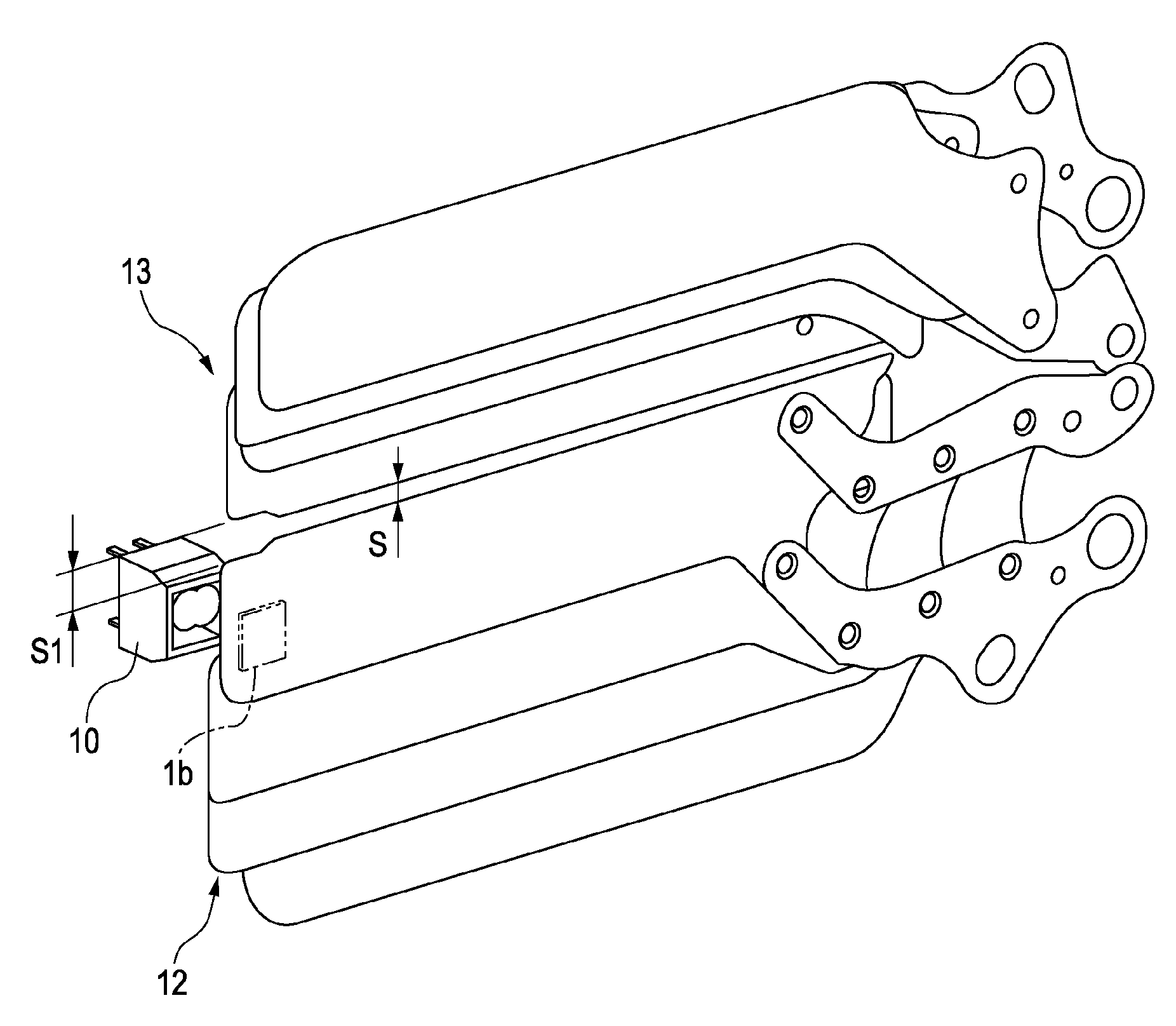
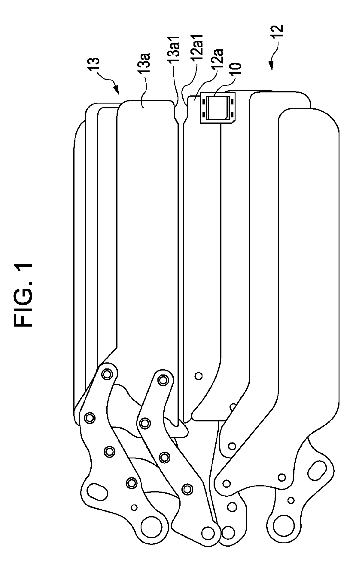
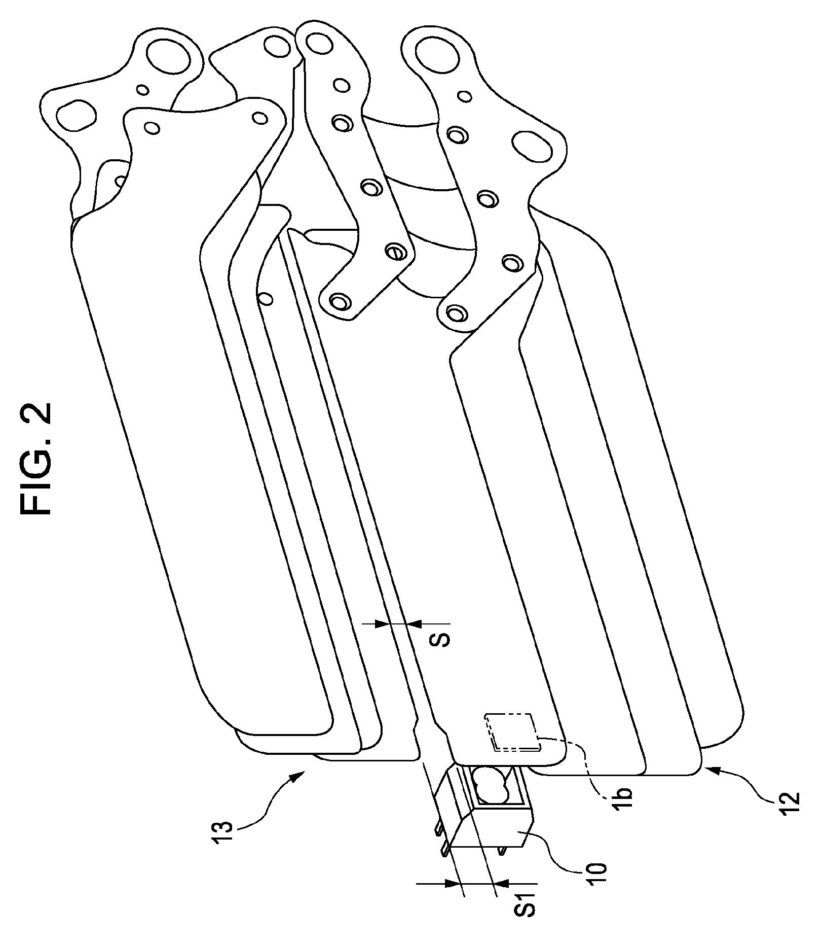
[0039]FIG. 1 is a front view of an example structure of a main portion of a focal-plane shutter according to the exemplary embodiment of the present invention. FIG. 2 is a perspective rear view thereof, showing a state in which the shutter is traveling. For simplifying reasons with regard to FIGS. 1 and 2, a shutter bottom plate is not shown.

[0040]In FIGS. 1 and 2, reference numeral 12 denotes a first blade unit, and reference numeral 13 denotes a second blade unit. Reference numeral 12a denotes a first blade of the first blade unit 12, and reference numeral 13a denotes a first second blade of the second blade unit 13. Second to fourth blades, a main blade arm, and a sub blade arm of the first blade unit 12, and second to fourth blades, a main blade arm, and a sub blade arm of the second blade unit 13 are the same as those of the related example, so that they will not be described below.

[0041]The first blade 12a and the first second blade 13a have respective cut-away portions 12a1 a...


PUM


Abstract

A shutter device includes a blade member and a detecting unit. The blade member includes a first blade, a second blade, a detection portion, and a limiting portion. The blade member controls a time of exposure, performed on a recording medium, on the basis of a magnitude of a width of a slit. The slit includes slit portions and is provided when the first and second blades travel. The slit portions are provided at the detection portion and limiting portion, respectively. The detecting unit detects a state of the slit width. A cut-away portion is provided at the blade member so that a width of the slit portion at the detection portion is greater than a width of the slit portion at the limiting portion. The detection portion is detected by the detecting unit. The limiting portion limits the exposure time.

Description

BACKGROUND OF THE INVENTION[0001]1. Field of the Invention[0002]The present invention relates to a shutter device including a first blade and a second blade, and to an image pickup apparatus.[0003]2. Description of the Related Art[0004]In general, as a shutter used in a single lens reflex camera, a focal-plane shutter including two sets of light-shielding members, first blades (a first curtain) and second blades (a second curtain), is used. Prior to exposure, the first blades of the focal-plane shutter cover an aperture. Then, when shooting is performed, first, the first blades withdraw from the aperture to start the exposure on an image pickup surface. Thereafter, after a predetermined time, the shutter device operates so that the second blades cover the aperture.[0005]When a high-speed time control is performed at the focal-plane shutter, the width of a slit, formed by portions of the first blades and the second blades, is reduced to achieve the high-speed time control.[0006]Japan...

Claims


Application Information

Patent Timeline
IPC IPC(8): G03B9/10G03B9/36
CPCG03B9/10
Inventor NAMAI, AKIHIRO
Owner CANON KK
Why Eureka
Try Eureka