Microfluidic Device for Identification, Quantification, and Authentication of Latent Markers

a microfluidic device and latent marker technology, applied in the field of identification and authentication, can solve the problems of limiting the rapid identification and quantification of a covert additive or feature, the bulky of machines and tools, and the difficulty of performing any type of identification, quantification or authentication in situ

Inactive Publication Date: 2008-05-22
AUTHENTIX INC
View PDF99 Cites 100 Cited by
  • Summary
  • Abstract
  • Description
  • Claims
  • Application Information

AI Technical Summary

Benefits of technology

[0022]The terms “a” and “an” are defined as one or more unless this disclosure explicitly requires otherwise. The terms “substantially,”“about,” and variations thereof are defined as being largely but not necessarily wholly what is specified as understood by one of ordinary skill in the art, and in one non-limiting embodiment, “substantially” refers to ranges within 10%, 5%, 1%, or 0.5% of what is specified. The term “coupled” is defined as connected, although not necessarily directly, and not necessarily mechanically.
[0023]The terms “comprise” (and any form of comprise, such as “comprises” and “comprising”), “have” (and any form of have, such as “has” and “having”), “include” (and any form of include, such as “includes” and “including”) and “contain” (and any form of contain, such as “contains” and “containing”) are open-ended linking verbs. As a result, a method or device that “comprises,”“has,”“includes” or “contains” one or more steps or elements possesses those one or more steps or elements, but is not limited to possessing only those one or more elements. Likewise, a step of a method or an element of a device that “comprises,”“has,”“includes” or “contains” one or more features possesses those one or more features, but is not limited to possessing only those one or more features. Furthermore, a device or structure that is configured in a certain way is configured in at least that way, but may also be configured in ways that are not listed.

Problems solved by technology

While overt additives or features are readily identifiable, covert additives and features are not.
Among other limitations, current technologies limit rapid identification and quantification of a covert additive or feature.
In addition, many of the machines and tools are bulky and not available outside of a laboratory setting, making it difficult to perform any type of identification, quantification, or authentication in situ.
Further, there is an increased risk of handling and contamination and the burden of additive waste products.
As such, current practice for the identification and authentication of one or more covert markers in a material may be time consuming, error-prone, and expensive.

Method used


Image

  • Microfluidic Device for Identification, Quantification, and Authentication of Latent Markers
  • Microfluidic Device for Identification, Quantification, and Authentication of Latent Markers
  • Microfluidic Device for Identification, Quantification, and Authentication of Latent Markers

Examples


example 1

The Effect of Flow Rate

[0073]The rate of transformation (from latent to active form) often depends on the flow rate through the microfluidic cell. For example, lower flow rates may allow for improved and increased diffusion of the markers from the liquid (e.g., a fuel) to the transforming agent, and thus, higher fluorescent signals may typically be detected. In addition, the extent of transformation and signal level often depends on channel volume and quantity of the transformable marker. In some embodiments, capillary and channel diameters may also affect reaction time.

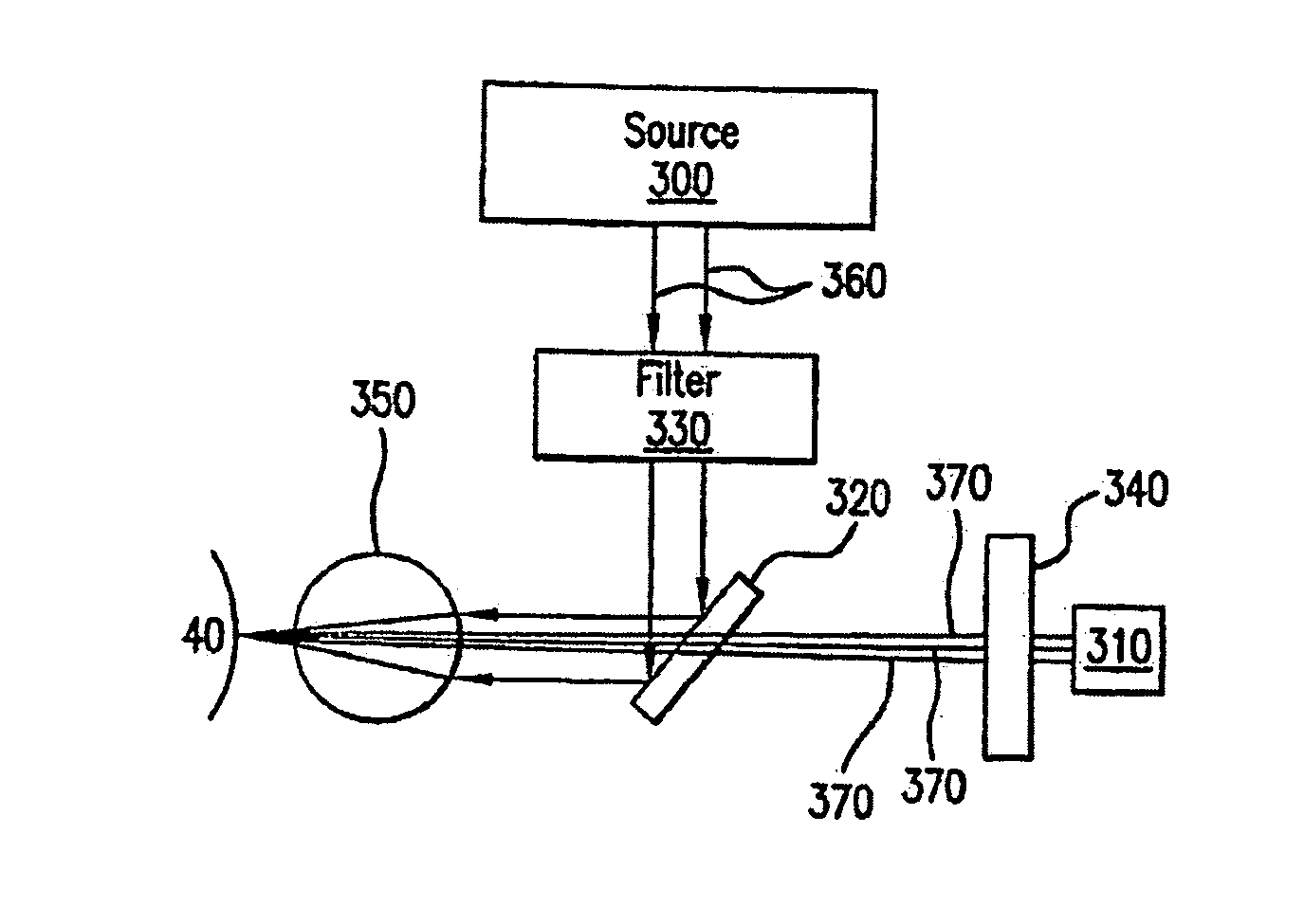
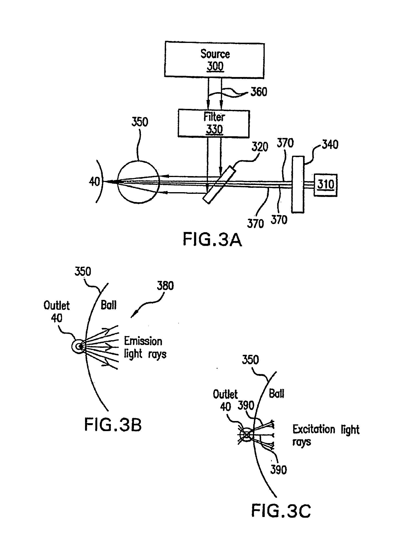
[0074]A fluorescent signal was detected using a detector / detection assembly similar to that described in FIG. 3A. Components of the system were housed in a machined plastic unit. A BrightLite filter set (Semrock, New York) optimized for measuring green fluorescent protein (GFP) was used. A light emitting diode (Roithner Lasertechnik, Austria) with a maximum output of about 470 nm was used as the source. The sensor ha...

example 2

Authenticating Potable Ethanol

[0078]Potable ethanol is often adulterated illegally with lower grade, and thus poses a need for a reliable, robust, and convenient authentication method. In this example, non-potable ethanol was marked with a covert marker and used to enable identification and authentication of potable ethanol adulterated with the non-potable form.

[0079]The marker used to identify non-potable ethanol was fluorescein diacetate, a marker that has no significant fluorescence when dissolved in ethanol. While fluorescein diacetate was used, any suitable marker with similar properties may be used. This includes markers that reside in an inactive form and may be transformed to an active form that is identifiable and quantifiable by a detector. Fluorescein diacetate may be transformed (via hydrolysis) in alkaline solutions to produce fluorescein to an active form with light-emitting properties that are detectable by an appropriate light detector.

[0080]In one example of the pre...

example 3

Plug Flow

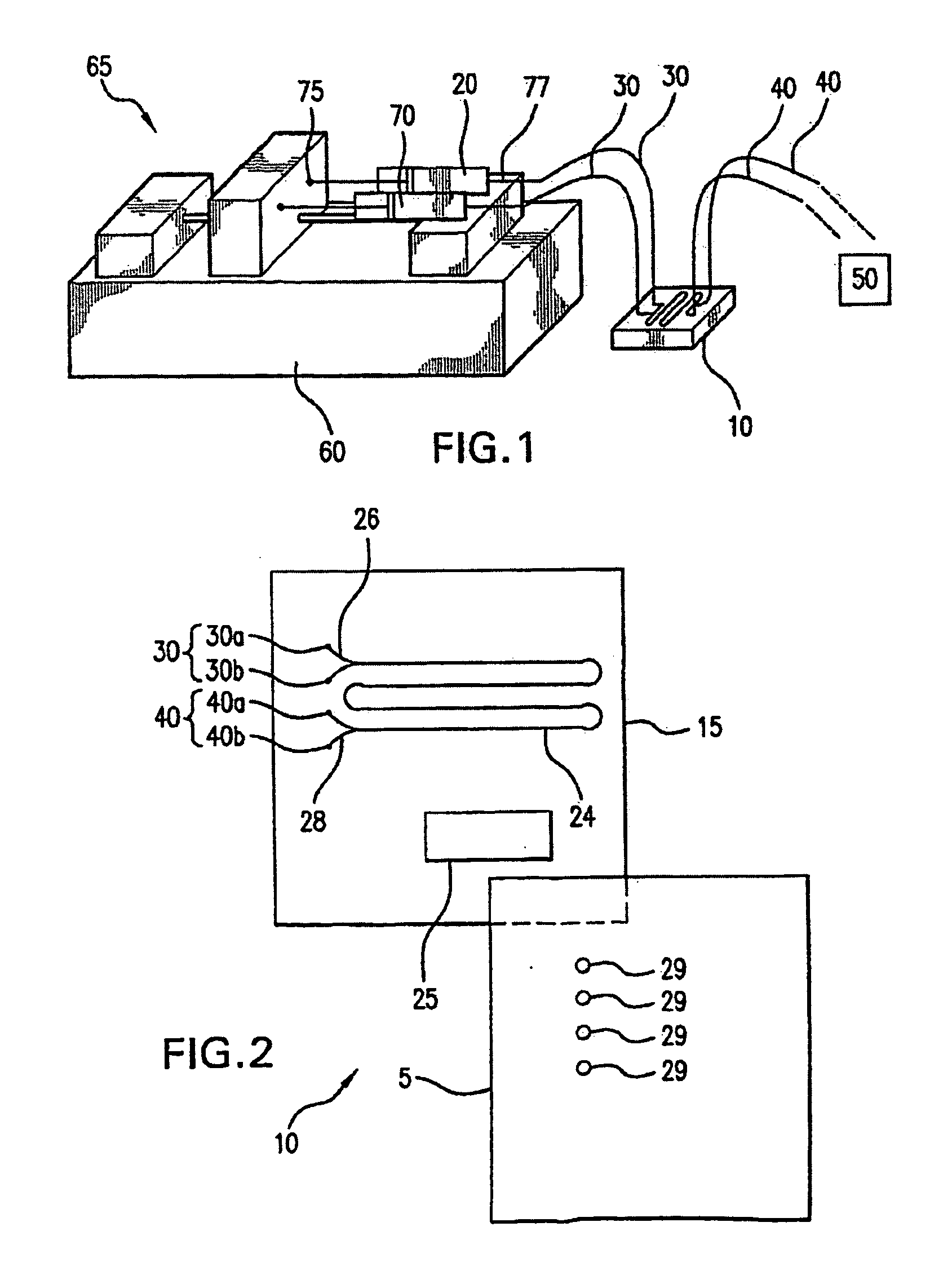
[0083]In one embodiment, system 65 of FIG. 1 may be modified to include a reservoir / mixer for providing a plug flow. In one respect, a material comprising latent markers and a first agent (e.g., aqueous ethanol) that may transform the latent markers may be introduced to a microfluidic cell using techniques described above (e.g., using a pump system and the like). The introduction of the material simultaneously with the agent provides a laminar flow.

[0084]In one respect, the material may subsequently be split from the latent markers and removed via an outlet (e.g., outlet 40 of FIG. 2), leaving only the latent markers. For example, referring to FIG. 7, as the material 700 and markers 702 flow through the microchannel 24, the markers may penetrate through the interface 704 into the first agent 706, and thus at the split 708, the material may be subsequently removed, leaving the marker 702 and first agent 706. In one respect, a driving equilibrium (e.g., pH levels) may be adju...


PUM

PropertyMeasurementUnit
depthaaaaaaaaaa
widthaaaaaaaaaa
widthaaaaaaaaaa

Abstract

Devices and methods for identification, authentication, and quantification of one or more covert markers in a material are disclosed. A device includes a microfluidic cell, a liquid transfer system, and a detector system and is an integrated unit providing an automated, in-line process for identifying one or more materials containing at least one latent marker that may transform into an active form. The microfluidic cell is for receiving a material containing a latent marker and has at least one inlet for receiving one or more liquids and one or more outlets through which liquids exit. The liquid transfer system is operably connected to the microfluidic cell and delivers liquids to the microfluidic cell. The detector system is proximate to the outlets for detecting the active form of the marker. With the device, a number of independent processing and analytic steps are combined onto a single, portable unit.

Description

RELATED APPLICATIONS[0001]This application is a continuation of, and claims priority under 35 U.S.C. 365(a) from, International Application No. PCT / US2006 / 008217, filed Mar. 8, 2006, which claimed priority from U.S. Provisional Patent Application Ser. No. 60 / 659,669, filed Mar. 8, 2005. Both priority applications are incorporated herein in their entirety.BACKGROUND OF THE INVENTION[0002]1. Field of the Invention[0003]The present invention relates generally to the field of identification and authentication. More particularly, the present invention relates to methods and devices for identification, quantification, and authentication of one or more materials, especially those containing one or more covert markers.[0004]2. Description of Related Art[0005]Identification and authentication of solid and / or liquid materials may use many techniques, including the use of overt or covert features or additives, such as colorants and dyes, e.g., tracers or markers. The overt or covert features o...

Claims


Application Information

Patent Timeline
Patent Type & Authority Applications(United States)
IPC IPC(8): G01N21/66B01J19/00G06G7/48B01L99/00
CPCB01L3/502776B01L3/502784B01L2200/0636G01N27/44721B01L2300/0816B01L2400/0487G01N21/17B01L2200/0673
Inventor EASTWOOD, IANAL-JAFARI, MOHAMMEDDORLAND, ERWINGOODALL, DAVIDBERGSTROM, EDMUND T.TAYLOR, ANDREW
Owner AUTHENTIX INC
Why Eureka
Try Eureka