Bandaging structure and methodology

Inactive Publication Date: 2008-05-22
MJD INNOVATIONS
View PDF33 Cites 11 Cited by
  • Summary
  • Abstract
  • Description
  • Claims
  • Application Information

AI Technical Summary

Benefits of technology

[0010]Wound bandaging/dressing foam structure including a low rebound, temperature-conforming, acceleration-rate-sensitive cushioning expanse applicable to wound-proximate-associated anatomical tissue to apply a prede

Problems solved by technology

Uneven pressure distribution and local stagnation lead to the suppression of flow in the venous and lymphatic systems, increasing the risk of thrombosis and other problems related to circulation.
Occasionally, especially with post-operative restless patients, the bandage may be displaced, and may, on occasion, become totally unwrapped, which requires that the elastic bandage be repositioned, with further implied complications.
This is inconvenient, especially as the time-consuming band

Method used


Image

  • Bandaging structure and methodology
  • Bandaging structure and methodology
  • Bandaging structure and methodology

Examples


example 1

[0040]A knee replacement operation was performed on a patient. Such an operation is a severe intrusion into the body, in which the complete knee joint is replaced by an artificial joint. The access cut that is needed to perform this surgery is about 10 inches long. There is a significant amount of tissue separation involved in this operation as well as other traumatic events taking place at the same time, e.g., to the circulatory system. Fleece was applied to the wound, which was covered by a pressure pad of the invention, and the leg wrapped with an elastic bandage. After two days, a comparison of a patient who was bandaged using conventional techniques was compared to the patient bandaged using the pressure pad structure and methodology of the invention. The evaluation by the attending physician, who had performed the operations, was that there were significant differences between the two patients: (1) when opening the bandaging with the added foam two days after the operation, th...

example 2

[0042]A phlebectomy procedure, the removal of varicose veins, was treated post-operatively using the pressure pad and method of the invention. A sterile fleece provided a catch for blood coming out of the wound. A sterile, self-adhesive foil was applied to fix the fleece in place. A cotton sock, as commonly used with a plaster-cast, was used to cover the leg top-to-bottom as a separation layer under the foam. Then the foam was applied over the affected area of the leg and elastic bandaging applied on top of the foam to provide the needed pressure.

[0043]The comfort for the patient was very good. The pressure pad and method of the invention proved to be very useful, especially when using the CPM system, which is a critical part of rehabilitation following joint replacement, to allow for exercising the joint without muscle flexion / extension by the patient. The compression of the wounded area as well as the rest of the leg was very good. The tissue texture (appearance) for the areas cov...


PUM


Abstract

Wound bandaging/dressing foam structure including a low rebound, temperature-conforming, acceleration-rate-sensitive cushioning expanse applicable to wound-proximate-associated anatomical tissue to apply a predetermined expanse of substantially uniform, non-blood-flow-occluding pressure, accompanied by adjacent, included lateral extremities of this expanse which apply a gradually declining-to-zero anatomical-tissue pressure.

Description

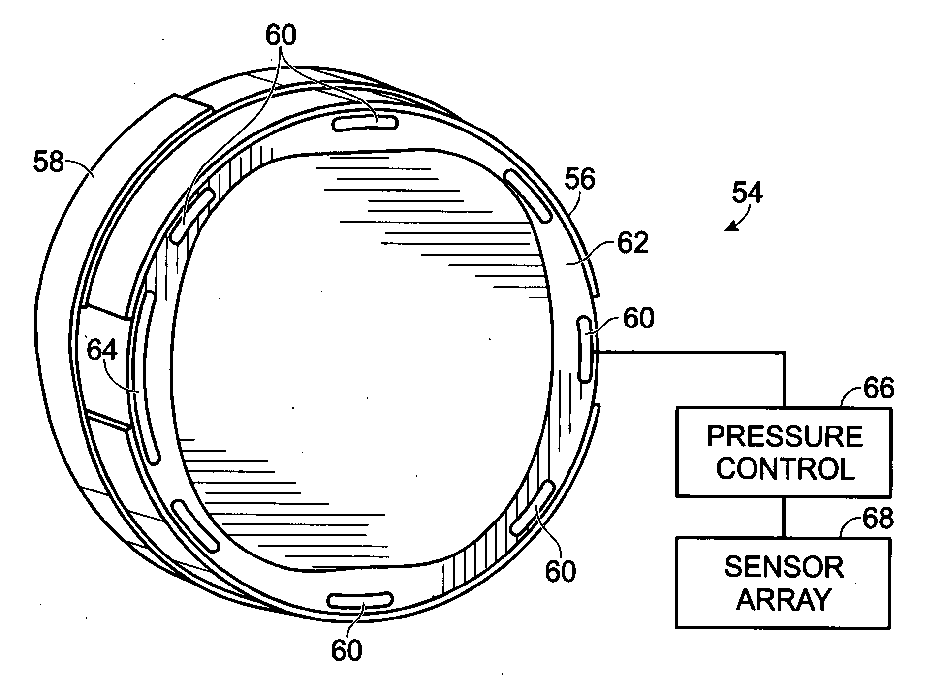
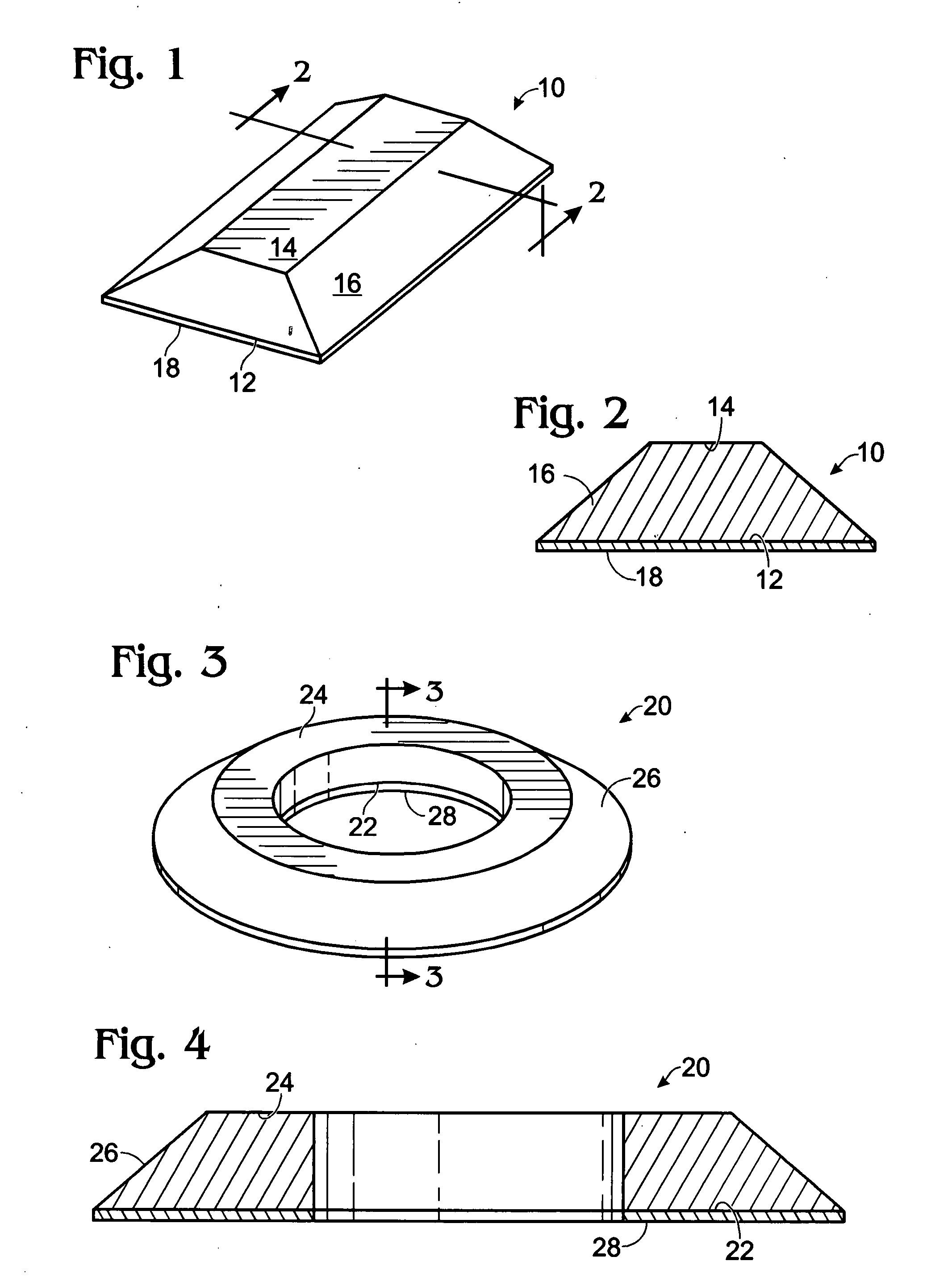
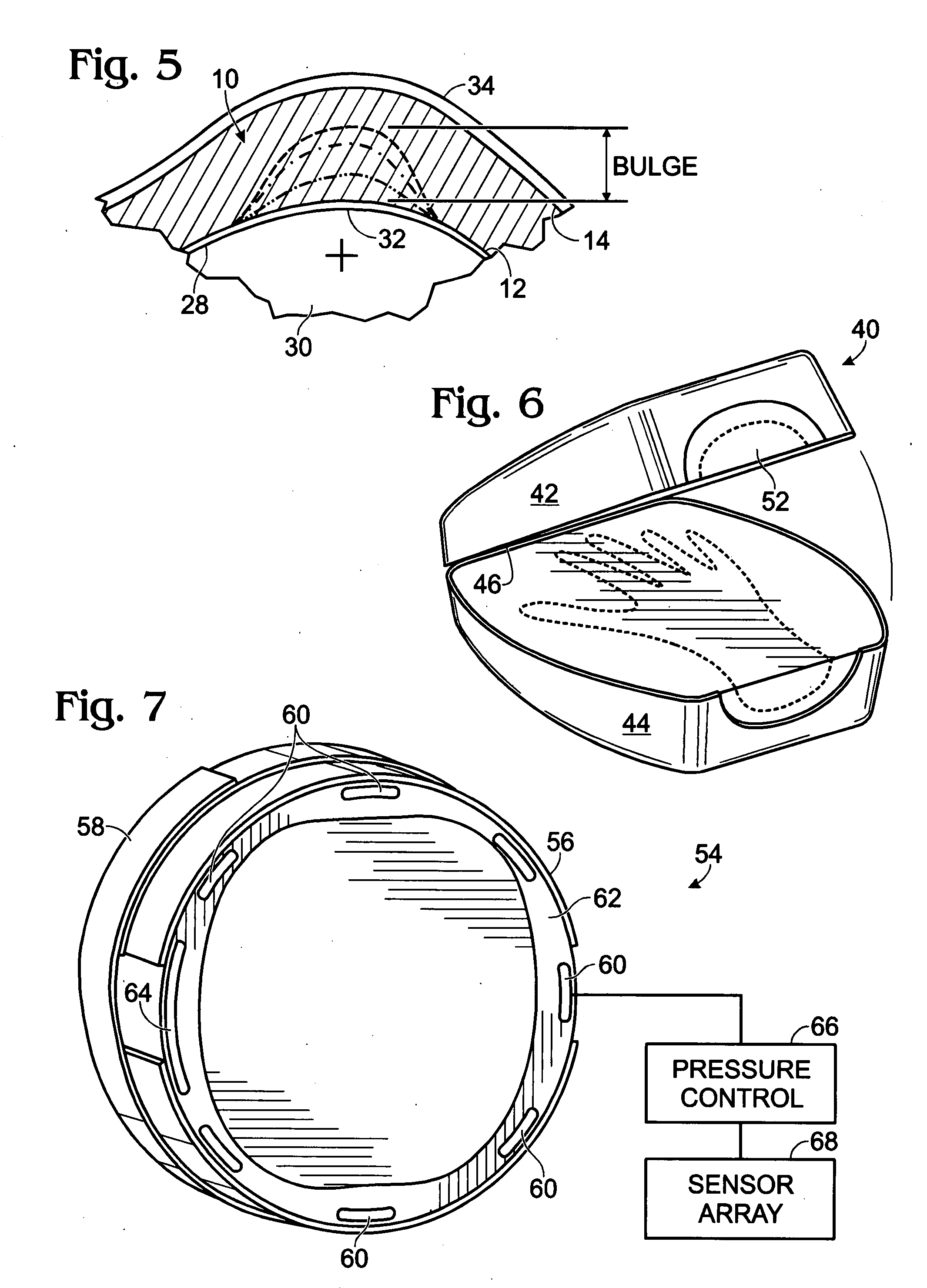
RELATED APPLICATIONS[0001]This patent application claims priority from U.S. Provisional Patent Application Ser. No. 60 / 859,770, for Bandaging Structure and Methodology, filed Nov. 16, 2006, which describes improvements and variations to the subject matter disclosed, illustrated and claimed in U.S. Pat. No. 6,812,375 B2, granted Nov. 2, 2004, for Pressure-evenizing Low-rebound Wound Dressing, the contents of the provisional patent application and the patent are incorporated herein by reference.FIELD OF THE INVENTION[0002]This invention relates to medical dressing for wounds, and specifically to a medical dressing which provides evenly distributed pressure about a wound site.BACKGROUND OF THE INVENTION[0003]A background description of the prior art is found in U.S. Pat. No. 6,812,375 B2. This application describes further improvements and modifications to the subject matter of the '375 patent. One improvement is the incorporation into an otherwise generally uniform-thickness, pressure...

Claims


Application Information

Patent Timeline
IPC IPC(8): A61F13/00
CPCA61F13/00021A61F13/069A61F2013/0074A61F2013/0028A61F2013/00187
Inventor PAASCHE, GERHARD
Owner MJD INNOVATIONS
Why Eureka
Try Eureka