Method and Apparatus For Wheel Assembly Force Moment Arm Measurement

a technology of force moment and measurement method, which is applied in the direction of vehicle wheel testing, structural/machine measurement, instruments, etc., can solve the problems of non-traditional vehicle wheel alignment, unfulfilled utilization of advanced measurement capabilities of machine vision alignment system, and inability to meet the needs of vehicle wheel alignmen

Inactive Publication Date: 2008-05-22
HUNTER ENG
View PDF6 Cites 41 Cited by
  • Summary
  • Abstract
  • Description
  • Claims
  • Application Information

AI Technical Summary

Benefits of technology

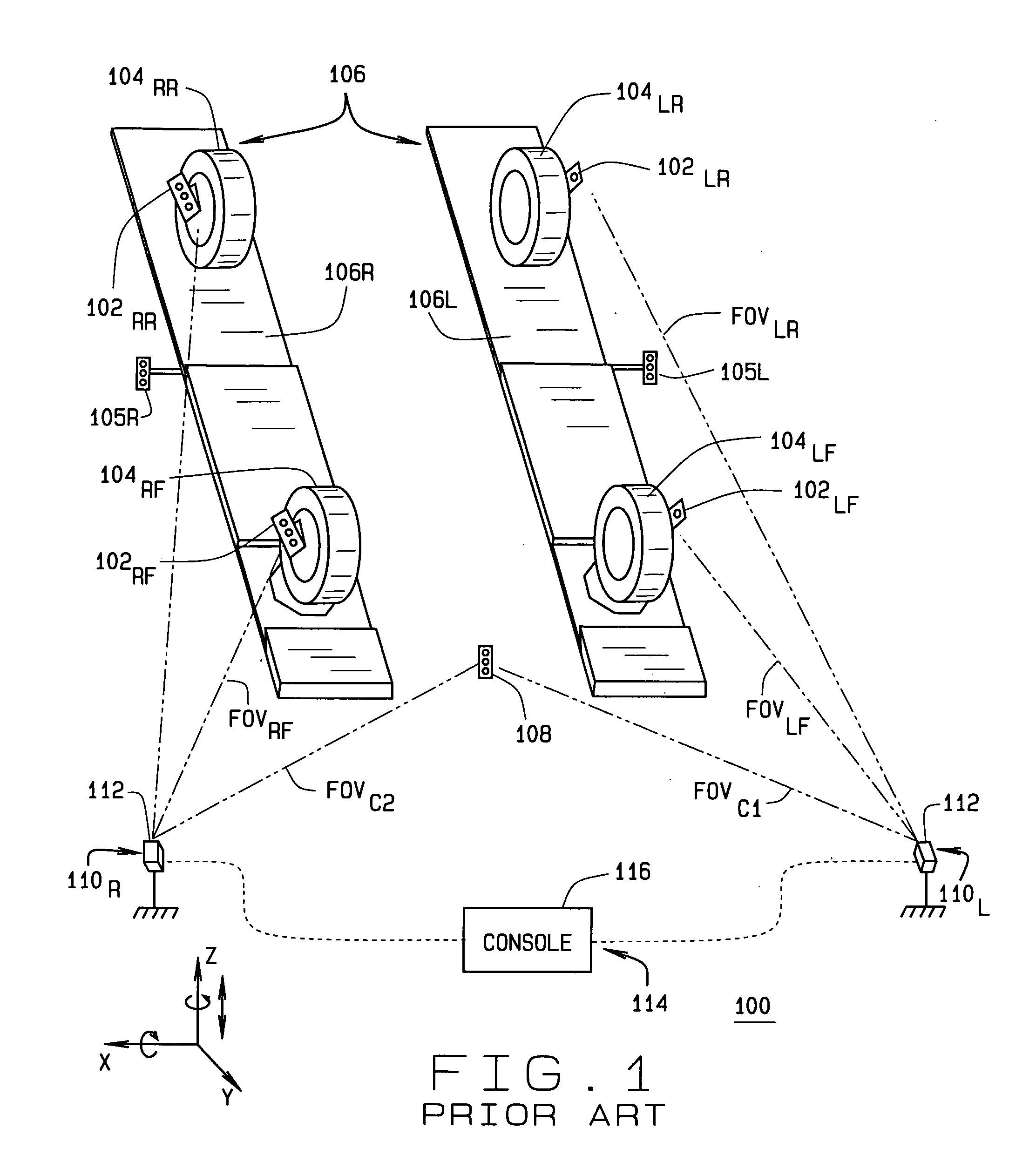
[0008]Briefly stated, the present disclosure provides a vehicle wheel alignment system with the capability to make non-traditional vehicle wheel alignment and suspension geometry measurements in order to determine dynamic behavior of a vehicle suspension system. The vehicle wheel alignment system is configured to characterize the suspension geometry with respect to the body of the vehicle as well as to a rolling surface by measuring in three dimensions, points and/or angles on the vehicle body as well as the vehicle wheels. The vehicle wheel alignment system may observe targets, attached to the points of interest on the v

Problems solved by technology

In the wheel alignment industry the advanced measuring capabilities of machine vision alignment systems have not been fully utilized.
However, there are many non-traditional vehicle wheel alignment and suspension system measurements that are of interest to those involved in suspension system adjustment, modification or reconstruction that are not measurable with prior art vision alignment systems and measurement methods.
This may not be the case as a vehicle which has been properly statically aligned may exhibit a pull or bump steer during the road test

Method used


Image

  • Method and Apparatus For Wheel Assembly Force Moment Arm Measurement
  • Method and Apparatus For Wheel Assembly Force Moment Arm Measurement
  • Method and Apparatus For Wheel Assembly Force Moment Arm Measurement

Examples


example 1a

Audi A4

[0136]

0.5*1651+0.5*1651+2870*tan(2)=1651+88.7=1751 mm

[0137]With no dog tracking, the vehicle's wheels take up 1651 / 3658*100=45% of the road's lane.

[0138]With dog tracking, the vehicle's wheels take up 1751 / 3658*100=48% of the road's lane.

example 2a

Class 8 Truck

[0139]

0.5*2413+0.5*2413+6223*tan(2)=2413+217=2630 mm

[0140]With no dog tracking, the vehicle's wheels take up 2413 / 3658*100=66% of the road's lane.

[0141]With dog tracking, the vehicle's wheels take up 2630 / 3658*100=72% of the road's lane.

[0142]Body Overhang

[0143]The amount of front body overhang and rear body overhang also affect this dog tracking condition, as may be seen in FIG. 17. The amount of overhang can be measured with a ride height target placed even with the front of the vehicle and even with the rear of the vehicle. Placing the ride height target with the current vision system will likely put it out of the FOV of the cameras. Having the target held by a person to get an estimate of the front overhang would not be very good because a person would have a difficult time holding the target steady and it doesn't come across as a very accurate measurement. The better implementation is to use a stand that can flexibly hold the target. The stand would ideally have a ...

example 1b

Audi A4

[0145]

0.5*1651+0.5*1651+((2870+914+1067)*tan(2))=1651+169=1820 mm

[0146]With no dog tracking, the vehicle's wheels take up 1651 / 3658*100=45% of the road's lane.

[0147]With dog tracking, the vehicle's wheels take up 1820 / 3658*100=50% of the road's lane.


PUM


Abstract

A machine vision vehicle wheel alignment system configured to measure non-traditional vehicle wheel alignment angles and to determine dynamic behavior of a vehicle suspension system by observing optical targets or visible features, attached to points of interest on the vehicle body or vehicle wheels. The vehicle wheel alignment system characterizes the suspension geometry with respect to the body of the vehicle and to a rolling surface by measuring, in three-dimensions, points and/or angles on the vehicle body as well as the vehicle wheels, enabling measurement of specific non-traditional vehicle parameters, including wheel assembly braking force and lateral force moment arms.

Description

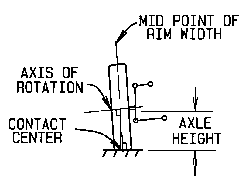
CROSS-REFERENCE TO RELATED APPLICATIONS[0001]The present application is a non-provisional of, and claims priority from, U.S. Provisional Patent Application Ser. No. 60 / 866,537 filed on Nov. 20, 2006, which is herein incorporated by reference.STATEMENT REGARDING FEDERALLY SPONSORED RESEARCH[0002]Not Applicable.BACKGROUND OF THE INVENTION[0003]The present invention is related generally to methods for vehicle wheel alignment, and in particular, to advanced methods for measuring non-traditional vehicle wheel alignment and suspension geometry measurements such as angles or distances including a wheel assembly braking force moment arm and lateral force moment arm.[0004]In the wheel alignment industry the advanced measuring capabilities of machine vision alignment systems have not been fully utilized. Traditional vehicle wheel alignment angles include camber, caster, toe, thrust line, and vehicle centerline measurements. However, there are many non-traditional vehicle wheel alignment and s...

Claims


Application Information

Patent Timeline
IPC IPC(8): G01M17/013
CPCG01B11/2755G01B2210/30G01B2210/143
Inventor STIEFF, MICHAEL T.BURNS, LEIGH R.DORRANCE, DANIEL R.GOLAB, THOMAS J.SHYLANSKI, MARK S.
Owner HUNTER ENG
Why Eureka
Try Eureka