Manual roller shade having clutch mechanism, chain guide and universal mounting

a clutch mechanism and roller shade technology, applied in the direction of shutters/movable grilles, door/window protective devices, curtain suspension devices, etc., can solve the problems of time-consuming and labor-intensive upgrading in order to replace a manual roller shade with a motorized roller shade,

Inactive Publication Date: 2008-05-29
LUTRON TECH CO LLC
View PDF22 Cites 114 Cited by
  • Summary
  • Abstract
  • Description
  • Claims
  • Application Information

AI Technical Summary

Benefits of technology

[0006]According to one aspect of the present invention, a clutch mechanism is provided for a manual roller shade having a roller tube adapted for winding receipt of a flexible shade fabric. The clutch mechanism comprises a rotatably supported sprocket adapted to receive a drive chain for rotation of the sprocket in response to application of an input force to the drive chain and an output member adapted for engagement with the roller tube. The clutch mechanism also comprises a gear train coupled between the sprocket and the output member for transmitting rotation of the sprocket to rotation of the output member. The gear train includes a sun gear, a plurality of planet gears rotatably mounted on a planet carrier and meshingly engaging the sun gear, and a ring gear meshingly engaging the planet gears. The sun gear and the ring gear rotate during actuation of the gear train while the planet carrier is held against rotation. The clutch mechanism is characterized by a sprocket ratio representing a ratio between the diameter of the sprocket and the diameter of the roller tube selected such that mechanical advantage of the gear train is offset to provide an effective gear ratio for the gear train of approximately 2:1.

Problems solved by technology

Traditionally, manufacturers of motorized roller shades do not manufacture manual roller shades, and vice versa.
As a result, upgrading in order to replace a manual roller shade with a motorized roller shade is rendered difficult and time consuming because incompatible mounting hardware of the manual roller shade must be replaced with, or supplemented by, mounting hardware adapted for the motorized roller shade.

Method used


Image

  • Manual roller shade having clutch mechanism, chain guide and universal mounting
  • Manual roller shade having clutch mechanism, chain guide and universal mounting
  • Manual roller shade having clutch mechanism, chain guide and universal mounting

Examples


Embodiment Construction

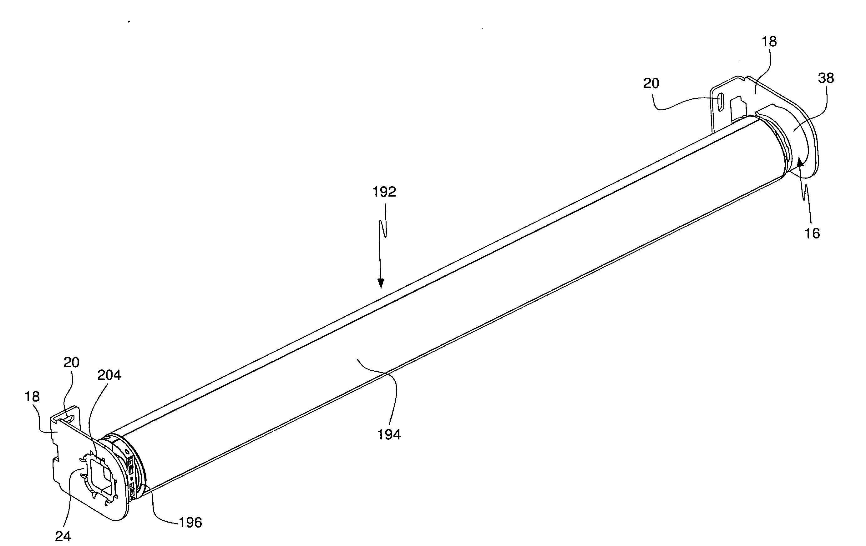
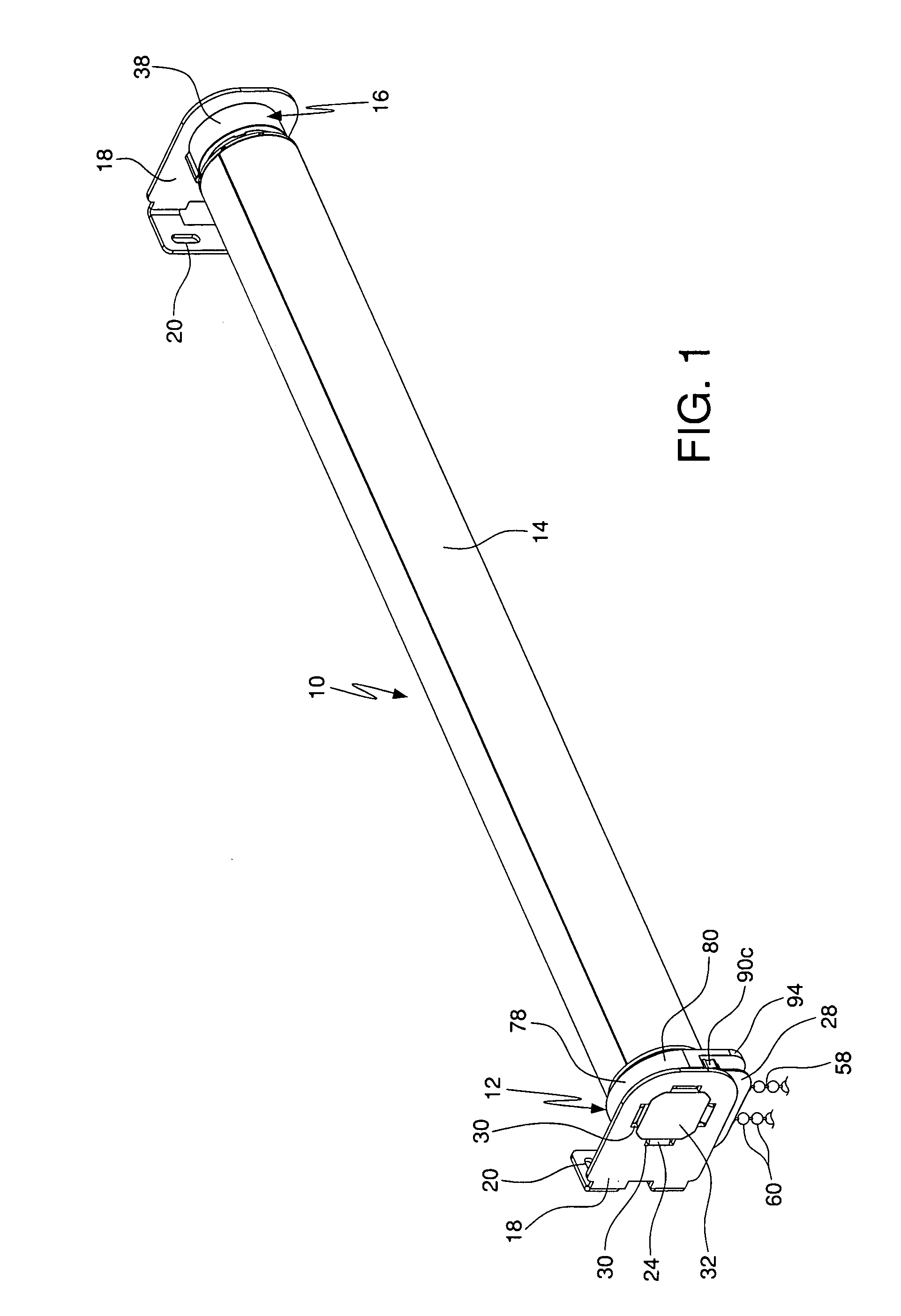
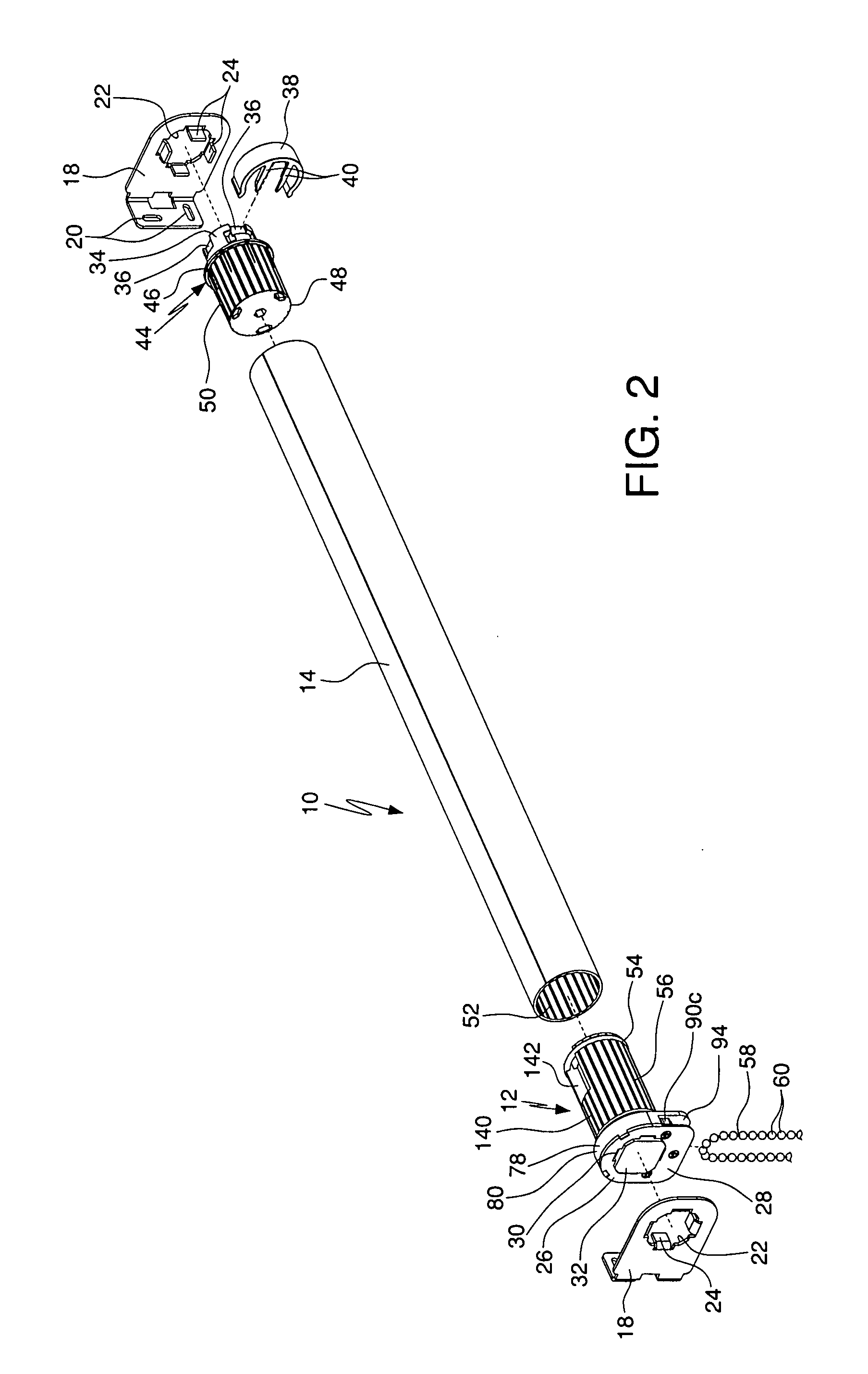
[0030]Referring to the drawings, where like numerals identify like elements, there is illustrated in FIG. 1 a manual roller shade 10 according to an exemplary embodiment of the invention including a clutch mechanism 12 that is bi-directional to provide for raising and lowering of a flexible shade fabric (not shown) windingly supported by an elongated roller tube 14 of the roller shade 10. The attachment of flexible shade fabrics to roller shade tubes is well known and no further description is required. As described below in greater detail, the clutch mechanism 12 is adapted to rotatingly drive the roller tube 14 of the roller shade 10 and to prevent back-driving of the roller tube 14 of the manual roller shade 10 that could otherwise occur, for example, if a pulling force was applied to a lower end of a flexible shade supported by the roller tube 14.

[0031]The clutch mechanism 12 is located adjacent a first end of the roller tube 14 on the left hand side of the view shown in FIG. 1....


PUM

PropertyMeasurementUnit
diameteraaaaaaaaaa
flexibleaaaaaaaaaa
input forceaaaaaaaaaa

Abstract

A manual roller shade includes a clutch mechanism having a gear train transferring rotation of an input sprocket to rotation of an output member engaging a roller tube. The gear train includes a sun gear, planet gears supported by a carrier and engaging the sun gear, and a ring gear engaging the planet gears. According to one embodiment, the carrier does not rotate. The ratio between the diameters of the input sprocket and the roller tube is selected to offset mechanical advantage of the gear train to provide an effective gear train ratio of approximately 2:1. A drive chain guide system includes spaced guide wheels controlling where a drive chain is suspended from the manual shade. A roller shade mounting system includes a bracket receiving either an input assembly of the manual roller shade or a motor of a motorized roller shade to facilitate conversion.

Description

CROSS-REFERENCE TO RELATED APPLICATION[0001]This application claims priority from U.S. provisional application No. 60 / 859,317, filed Nov. 16, 2006, the entire disclosure of which is hereby incorporated by reference.FIELD OF THE INVENTION[0002]The present invention relates to manual roller shades.BACKGROUND[0003]Roller shades include a flexible shade fabric windingly received on a roller tube for raising and lowering the shade fabric by rotating the roller tube. In manual roller shades, the rotation of the roller tube is provided by an input wheel that receives an input chain for converting a pulling force applied to the input chain into rotation of the input wheel. Manual roller shades include clutches having gear assemblies for transmitting the rotation of the input wheel to the rotation of the roller tube.[0004]Roller shade installations sometimes include a top treatment (e.g., fascia) for concealing the roller tube from view. It is typically necessary to notch the fascia and / or r...

Claims


Application Information

Patent Timeline
Patent Type & Authority Applications(United States)
IPC IPC(8): E06B9/58F16H57/08E06B9/68E06B9/56F16D67/02
CPCE06B9/72E06B9/78Y10T29/49716E06B2009/725E06B9/90
Inventor DETMER, BRANDON J.ADAMS, JASON O.
Owner LUTRON TECH CO LLC
Why Eureka
Try Eureka