

Decompression braking device in endothermic engines
- Summary
- Abstract
- Description
- Claims
- Application Information
AI Technical Summary
Benefits of technology
Problems solved by technology
Method used
Image

Examples
Embodiment Construction
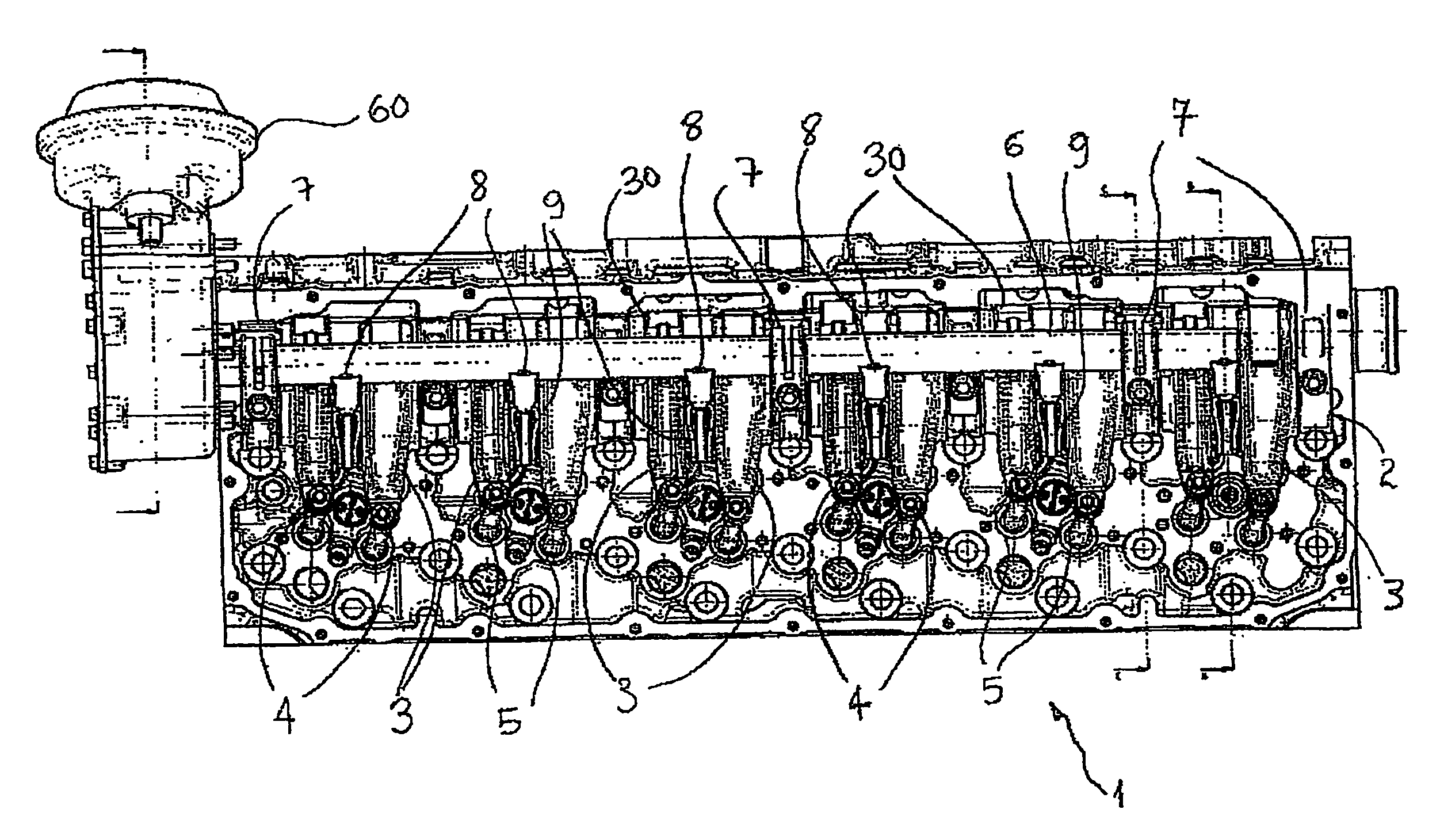
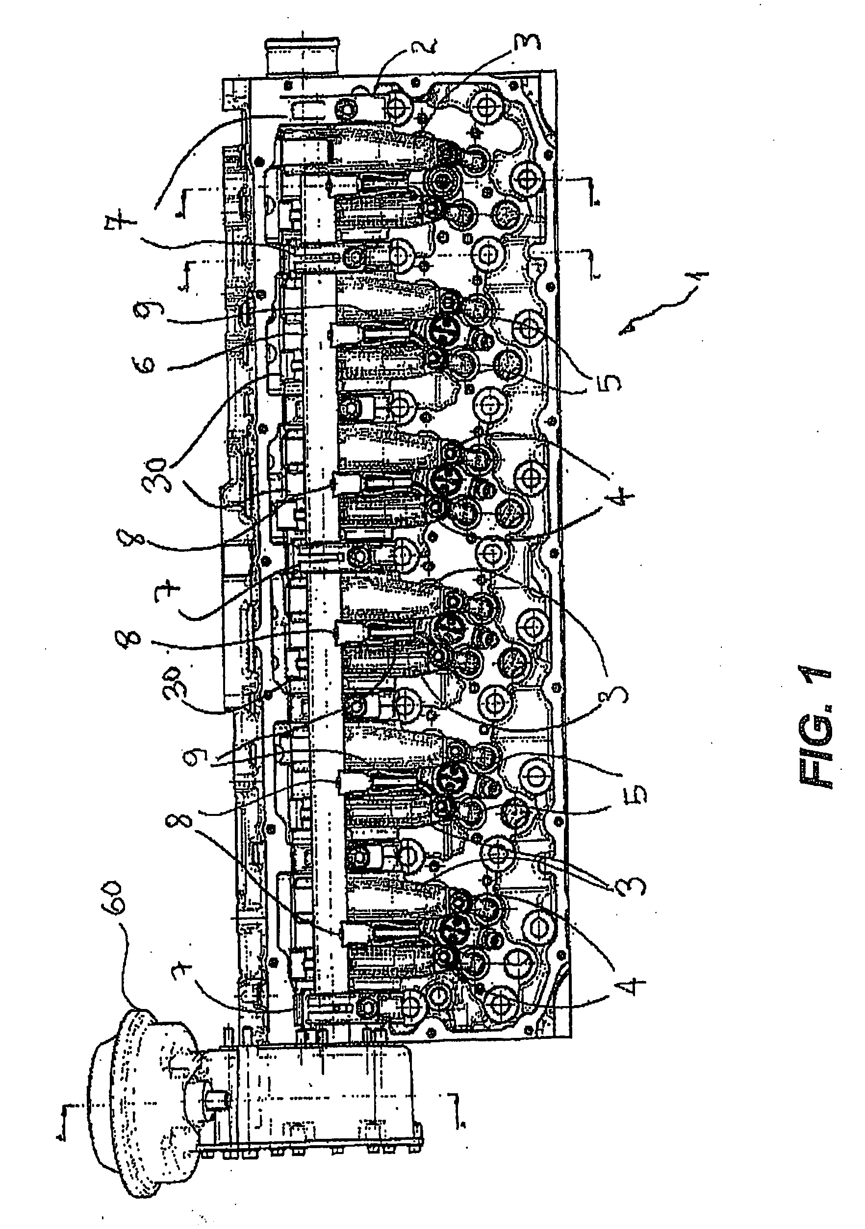
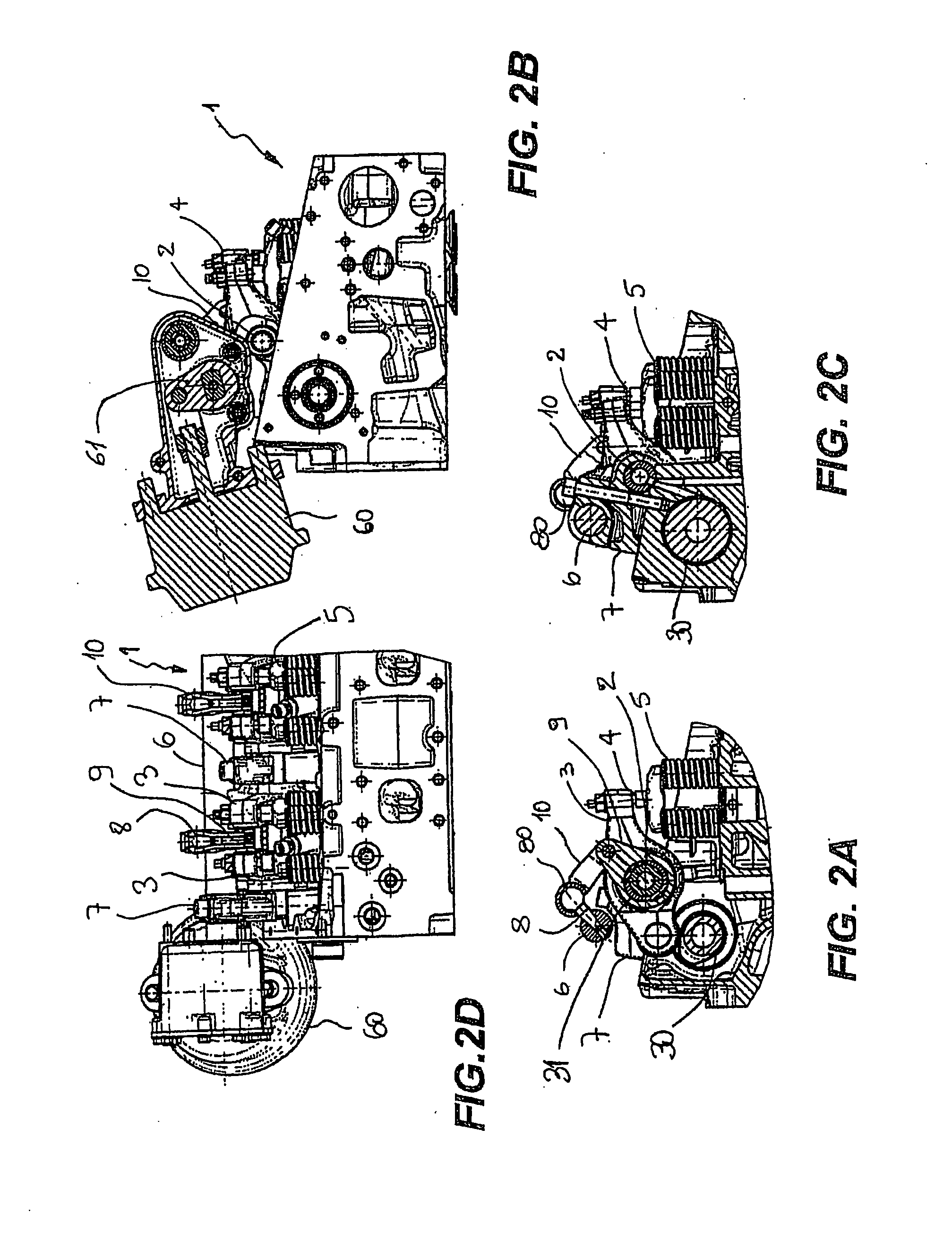
[0020]Referring now to FIG. 1, it is shown a head of an endothermic engine 1 which mounts the decompression braking device of the present invention. According to the invention, a lever axle 2 which rotationally mounts a plurality of levers 3 is provided, each lever 3 displays a tappet 4 which actuates one or more valves, in the case shown a pair of exhaust valves of which spring 5 is visible (actuation which occurs in a manner intrinsically already known and illustrated in better detail below). Each lever 3 is actuated by a corresponding cam integral with a camshaft 30 in the per se known manner.
[0021]A second actuating shaft 6 of the braking device according to the present invention is arranged on the top of lever axle 2. Shaft 6 is rotationally mounted on a corresponding plurality of supports 7 integrally arranged with the head of engine 1.
[0022]Furthermore, shaft 6 comprises a plurality of pins 8 integrally mounted on the first and each of which displays a spherically-shaped end ...
PUM
 Abstract
Description
Claims
Application Information