

Light emitter assembly
a technology of light emitting assemblies and components, applied in the direction of semiconductor devices for light sources, semiconductor/solid-state device details, lighting and heating apparatus, etc., can solve the problem of significant heat generation, achieve simple design, reduce the number of parts, and satisfy the effect of light dispersion or radiation pattern
- Summary
- Abstract
- Description
- Claims
- Application Information
AI Technical Summary
Benefits of technology
Problems solved by technology
Method used
Image

Examples
Embodiment Construction
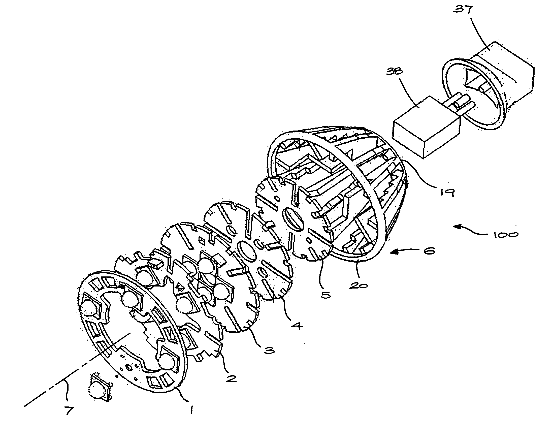
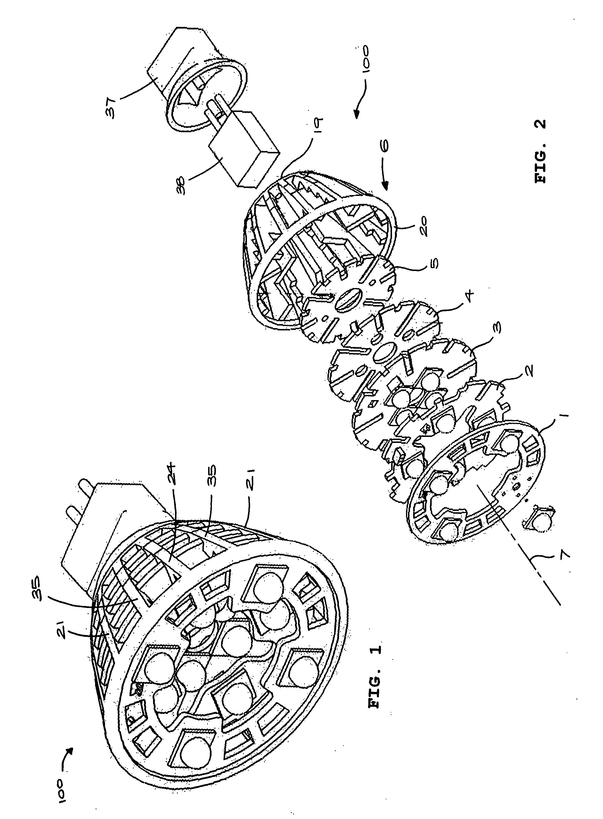
[0025]Referring to FIGS. 1 and 2, a light emitter assembly 100 includes three light emitter substrates 1, 2, 3 and two heat dissipating members 4, 5 which are stacked in a housing 6. The components 1-5 are substantially parallel, extending transversely relative to a central longitudinal axis 7. In the embodiment illustrated the LED substrates 1, 2, 3 and heat dissipating members 4, 5 are in a generally planar ring shape, but it will be understood that different shapes will be equally applicable depending upon the required application of the assembly.
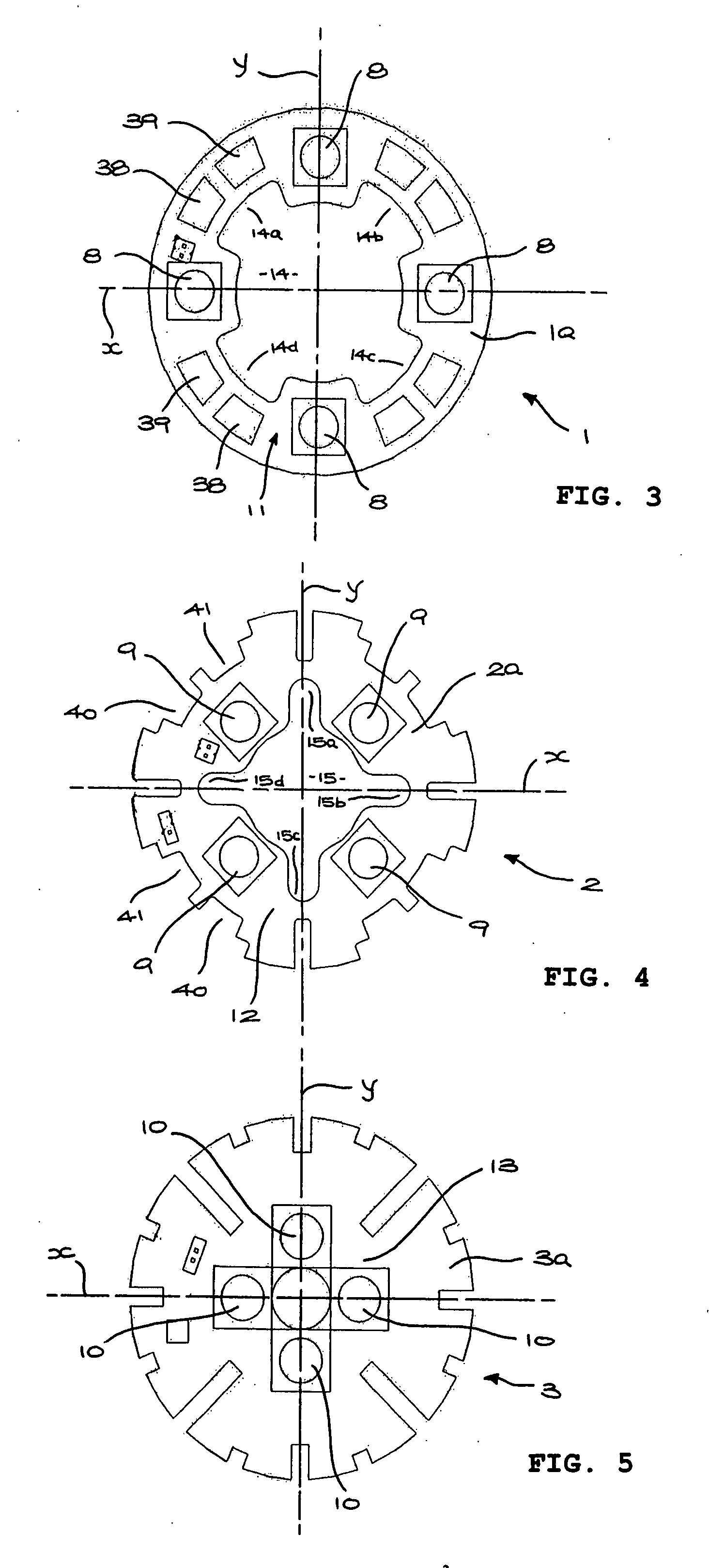
[0026]Each LED substrate 1, 2, 3 has an outer surface 1a, 2a, 3a and an opposing inner surface 1b, 2b, 3b. Four LEDs 8, 9, 10 are mounted on the respective outer surfaces 1a, 2a, 3a equally angularly spaced on respective pitch circles 11, 12, 13 centred on the central axis 7 and emitting light substantially parallel to the axis 7.
[0027]The LEDs on the three substrates 1, 2, 3 are offset radially, the pitch circle diameter 11 exceeding pi...
PUM
 Abstract
Description
Claims
Application Information