Eureka AIR delivers breakthrough ideas for toughest innovation challenges, trusted by R&D personnel around the world.

Cabinet With Removable Panel

Inactive Publication Date: 2008-05-29
ADRIAN HUMBERTO E
View PDF23 Cites 2 Cited by
  • Summary
  • Abstract
  • Description
  • Claims
  • Application Information

AI Technical Summary

Benefits of technology

[0014]Another object of the present invention is to provide a removable panel for a cabinet, whereby the removable panel can be quickly and easily removed and installed in the cabinet.
[0016]It is yet another object of the present invention to provide an electronics cabinet that permits quick access to the rear of the cabinet for installation of audio-video components, and further permits for closure of the rear of the cabinet after installation.
[0017]It is yet another object of the present invention to provide a removable panel for a cabinet that allows for the ventilation of the interior of the cabinet.
[0018]It is yet another object of the present invention to provide a removable panel for a cabinet that does not require hinges, or other expensive hardware.
[0019]It is yet another object of the present invention to provide a removable panel for a cabinet that allows for easy user access to the interior of the cabinet when the panel is removed.

Problems solved by technology

Audio-video systems, however, have become ever more complex, and increasingly include a number of separate audio-video components.
As a result, current audio-video systems require a large number of external wires for connecting the different components together.
Furthermore, each audio-video component typically requires an external source of electricity, further increasing the number of connections and wires.
As a result of this increasing complexity, audio-video systems are increasingly difficult to install, especially in the narrow confines of a cabinet.
This task is significantly complicated because almost all audio-video components have their connections in the rear.
Further complicating this task is the fact that many cabinets do not have an access point in the rear, or have only a minimal opening for passing electrical connections into and out of the cabinet.
Second, the user must provide a cable connection from outside the cabinet to the cable box inside the cabinet.
This task is very difficult for the average consumer, especially when she can not access the constituent connecting nodes on the audio-video components.
One disadvantage of this design, however, is that rear of the cabinet is open.
This is disadvantageous because the user can look directly through the cabinet system.
This problem is exacerbated when there is a light source behind the cabinet, or when the rear of the cabinet is not positioned against a wall because the connectors become increasingly more visible, resulting in audio-video system more aesthetically suited for the laboratory than an average family living room.
A disadvantage of such designs, however, is that they require one or more tools to remove the fasteners.
Furthermore, it takes a considerable amount of time to remove and reattach the fasteners.
Finally, there is always the possibility that the user may lose one or more fasteners during this process, thereby reducing the effectiveness of the system.
A disadvantage of such designs, however, is that it is difficult to access the rear of the audio-video components through the small hole.
This problem is exacerbated because the hole reduces the amount of illumination on the rear of the components.
A disadvantage of this solution is the high cost of the hardware necessary to hinge the panels.
This cost is especially prohibitive for high end cabinet systems, running upwards of $700.
Furthermore, while hinged rear panels do permit access to the rear of the cabinet, the opening is generally small and size relative to the audio-video components.

Method used


Image

  • Cabinet With Removable Panel
  • Cabinet With Removable Panel
  • Cabinet With Removable Panel

Examples


Embodiment Construction

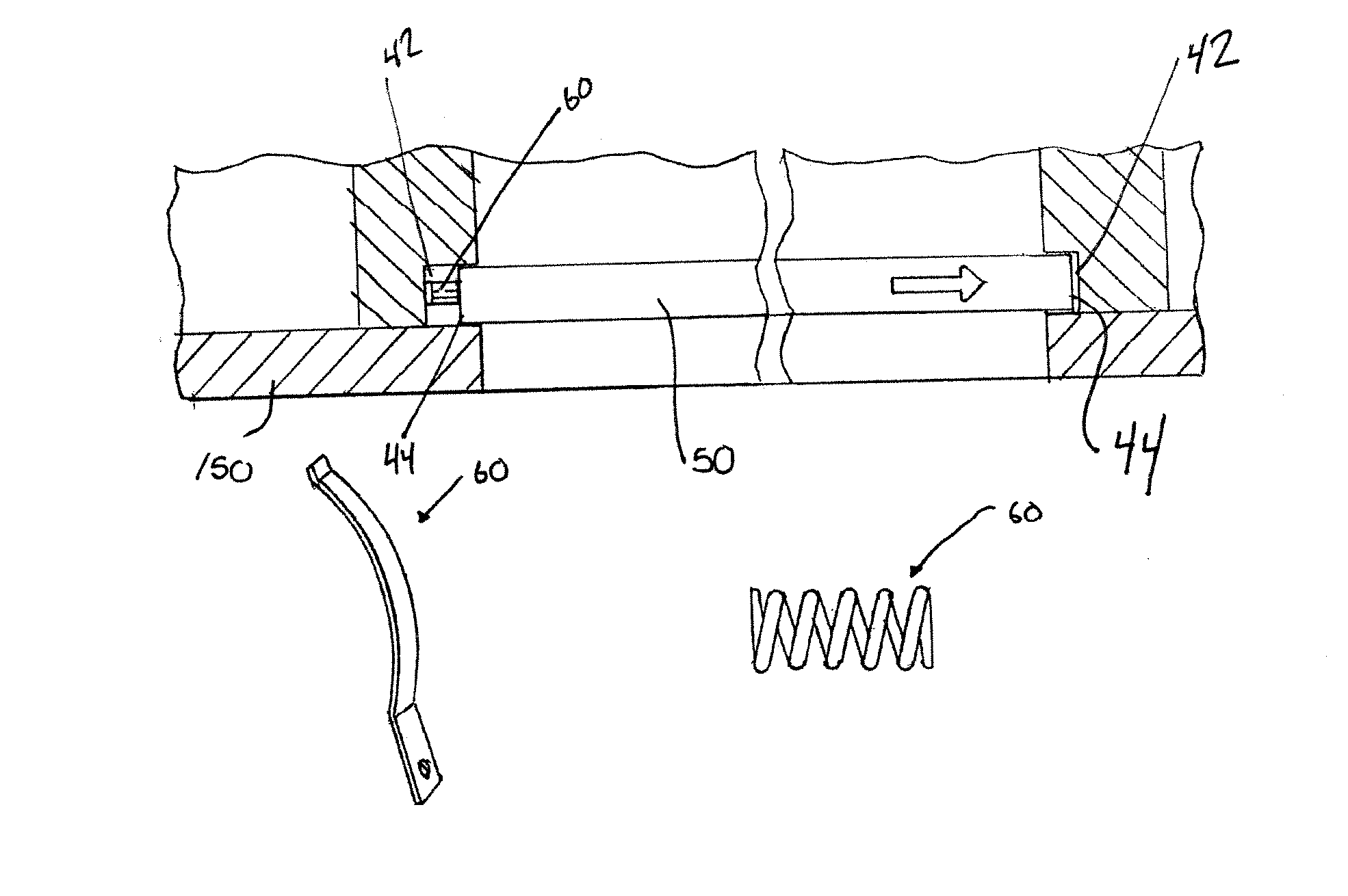
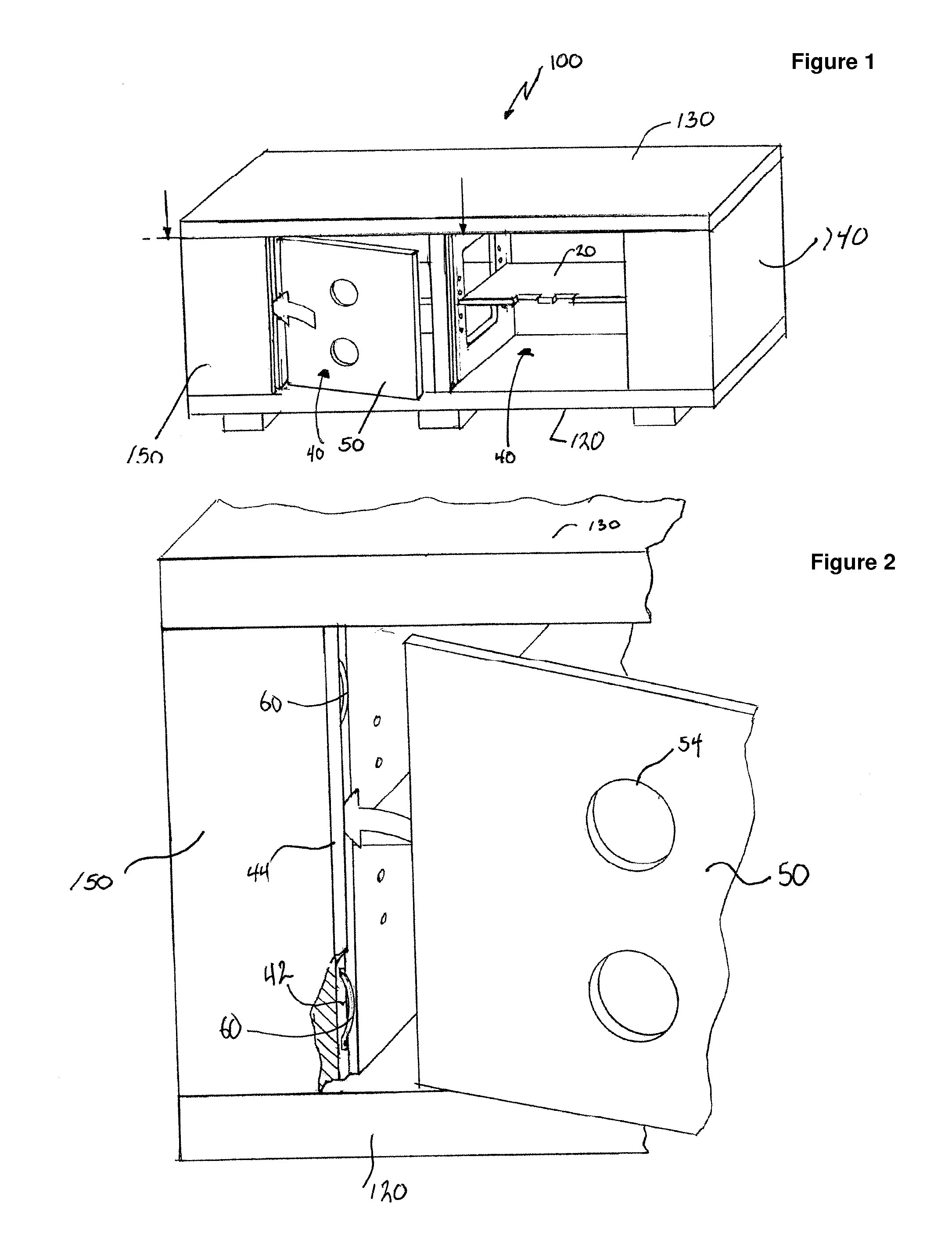
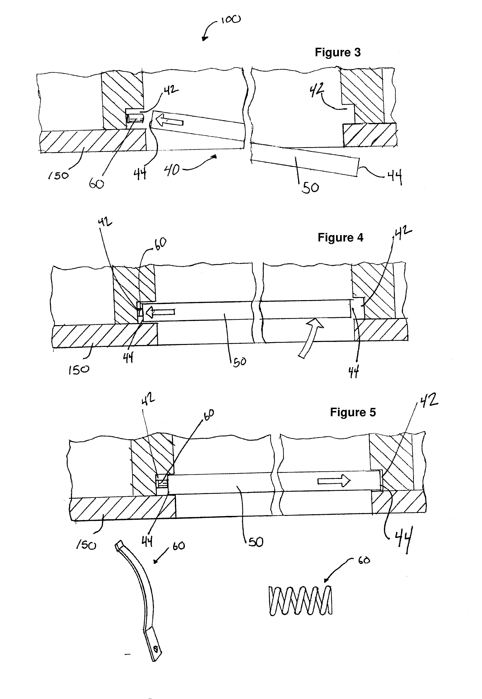
[0028]The invention disclosed herein contemplates a cabinet, specifically an electronics cabinet 100 in which a removable panel 50 can be removed from a window 40 or frame 40 in the rear panel 150 of the cabinet 100, providing unobstructed access to inside the cabinet 100 through the window 40 in the rear panel 150. An exemplary embodiment of the invention is illustrated in FIG. 1. The removable panel 50 can further be reinserted into window 40 of the rear panel 150 of the cabinet 100 so that the rear panel 150 appears as a continuous panel without windows 40, for example, as a solid panel. It should be understood that through out this detailed description the terms window 40 and frame 40 are used interchangeably.

[0029]In reference to FIG. 1 the electronics cabinet 100 includes a bottom panel 120, a top panel 130, two side panels 140, and a rear panel 150. These panels are substantially square or rectangular. The panels are preferably constructed of solid wood, or laminated wood, bu...


PUM


Abstract

The present invention relates to a closure assembly for an opening, and more specifically, a closure assembly for an opening in a cabinet. The closure assembly includes a frame defining an opening. The frame has a first side with a slot and a spring disposed in the slot. The frame also has a second side with a slot opposite from the first side. The closure assembly further includes a removable panel for closing the opening. The width of the removable panel is greater than the opening width. The panel is received in the first slot and the second slot, and the spring biases the removable panel into the second slot.

Description

CROSS-REFERENCE TO RELATED APPLICATIONS[0001]The present application claims the benefit of priority under 35 U.S.C. §119(e) to U.S. Provisional Application No. 60 / 867,634 filed on Nov. 29, 2006, entitled “Cabinet with Removable Panel,” the entirety of which is incorporated by reference herein.FIELD OF THE INVENTION[0002]The present invention generally relates to a cabinet with a removable panel and more particularly is related to an electronics cabinet with a closure assembly for an opening in the cabinet.BACKGROUND OF THE INVENTION[0003]Current audio-video systems, whether intended for the home or business, typically comprise a number of individual interconnected audio-video components. For example a modern home theater system may include a high definition television, cable box, DVD player, digital cable recorder, gaming system, and surround sound receiver. These components are interconnected with a series of external connections. The components are also connected to an external si...

Claims


Application Information

Patent Timeline
IPC IPC(8): A47B96/00
CPCA47B2096/207A47B96/20
Inventor ADRIAN, HUMBERTO E.
Owner ADRIAN HUMBERTO E
Why Eureka
Eureka Blog
Learn More