
Image forming apparatus capable of forming excellent image

Active Publication Date: 2008-05-29
KONICA MINOLTA BUSINESS TECH INC
View PDF5 Cites 3 Cited by
  • Summary
  • Abstract
  • Description
  • Claims
  • Application Information

AI Technical Summary

Benefits of technology

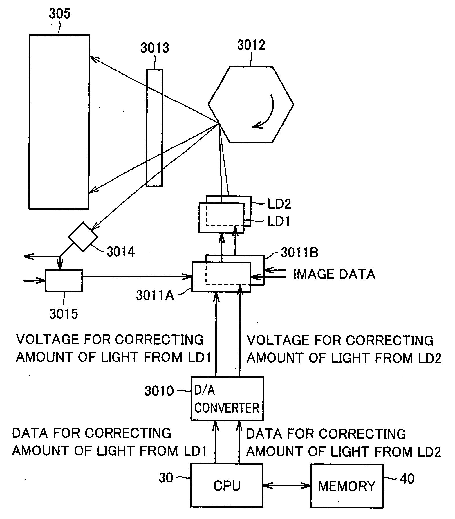
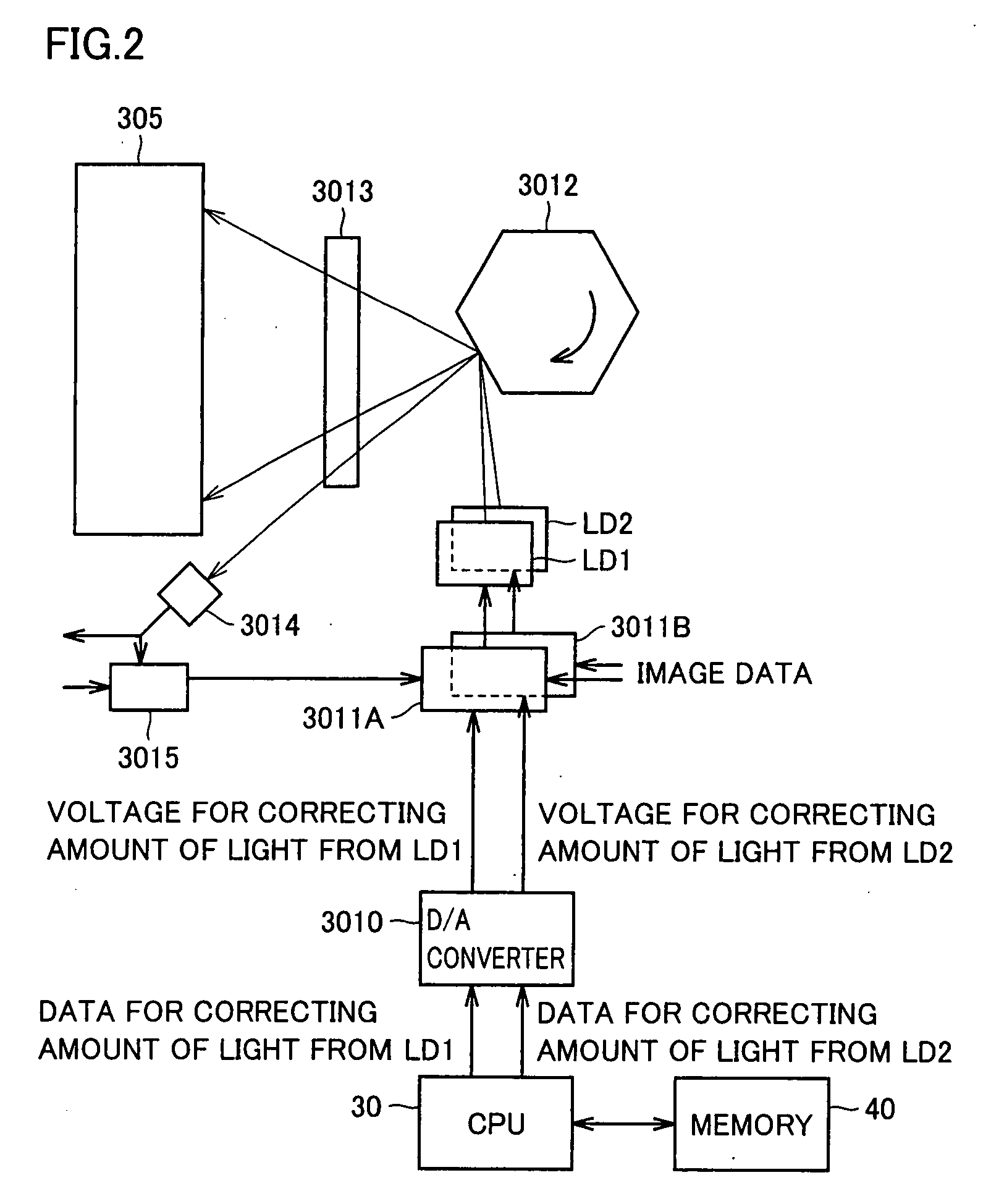
[0017]According to the present invention, in an image forming apparatus, a plurality of light sources are adjusted so as to obtain identical reproduction of dots by lasers. As a result, variation in density resulting from differing responsivities of the light sources can be suppressed, making it possible to form an excellent image.

Problems solved by technology

However, the method of adjusting the intensities of lasers from light sources, such as the one disclosed in Patent Document 1, is a method of adjusting the intensities of lasers when the light sources are fully exposed, and is not a method of making an adjustment such that identical reproduction of dots by lasers from light sources is obtained.
That is, even if the interval between one exposure-scanning and subsequent exposure-scanning is shortened as is disclosed in Patent Document 1, an adjustment cannot be made such that identical reproduction of dots by lasers from light sources is obtained, causing a problem that variation in density resulting from that occurs.

Method used


Image

  • Image forming apparatus capable of forming excellent image
  • Image forming apparatus capable of forming excellent image
  • Image forming apparatus capable of forming excellent image

Examples


Embodiment Construction

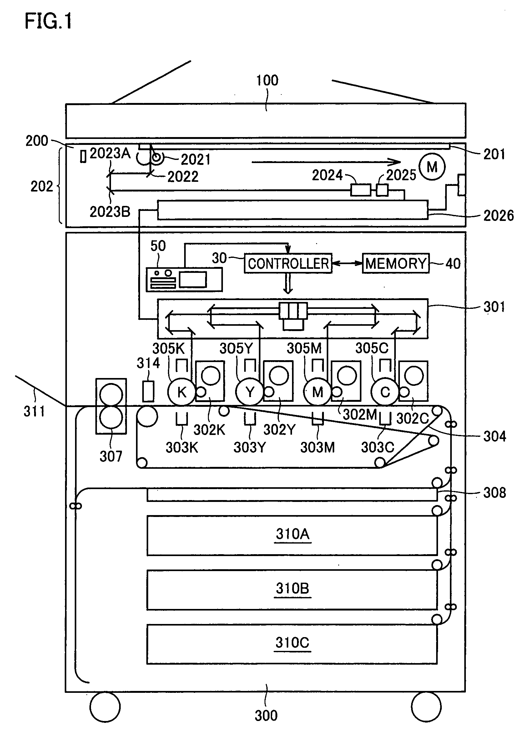
[0030]An embodiment of the present invention will be described below with reference to the drawings. In the following description, like parts and components are denoted by like reference numerals and the names and functions thereof are also the same.

[0031]In the present embodiment, the case in which an image forming apparatus according to the present invention is applied to a digital color copier using a tandem method (hereinafter, referred to as the “copier”) will be described. However, the image forming apparatus according to the present invention is not limited to a copier and may be a printer, a facsimile apparatus, a MFP (Multi Function Peripheral) which is a multifunction product into which a printer and a facsimile apparatus are integrated, or the like. In addition, a printing method is not limited to a tandem method or a digital method and the image forming apparatus may be a monochrome copier instead of a color copier.

[0032]An image forming apparatus using a tandem color me...


PUM


Abstract

Differing ratios of the amount of light from light source LD2 to the amount of light from light source LD1 are provided. An image pattern for adjustment that includes, for each color, an area made up of isolated dots by light source LD1 and an area made up of isolated dots by light source LD2, is printed for each ratio. In a copier, a density of each area is detected, a ratio at which a difference between the density of an area of isolated dots by light source LD1 and the density of an area of isolated dots by light source LD2 is smallest is decided as an adjustment ratio, and control is performed such that light sources LD1 and LD2 emit light at the adjusted ratio.

Description

[0001]This application is based on Japanese Patent Application No. 2006-318791 filed with the Japan Patent Office on Nov. 27, 2006, the entire content of which is hereby incorporated by reference.BACKGROUND OF THE INVENTION[0002]1. Field of the Invention[0003]The present invention relates to an image forming apparatus, an image forming method, and an image forming program product. More particularly, the present invention relates to an image forming apparatus, an image forming method, and an image forming program product that create an image by a plurality of exposure light sources.[0004]2. Description of the Related Art[0005]In recent years, in an electrophotographic image forming apparatus such as an MFP (Multi Function Peripheral), in order to improve resolution, a multi-beam exposure method is often adopted in which by using a plurality of exposure light sources an image is created on a single image carrier. A representative multi-beam exposure method includes a two-beam exposure...

Claims


Application Information

Patent Timeline
IPC IPC(8): B41J2/47
CPCB41J2/473
Inventor SAKAI, TETSUYAAKASHI, HIRONORI
Owner KONICA MINOLTA BUSINESS TECH INC
Learn More