Light deflector device and image forming apparatus
- Summary
- Abstract
- Description
- Claims
- Application Information
AI Technical Summary
Benefits of technology
Problems solved by technology
Method used
Image
Examples
example
[0067]Now, the present invention will be described further by way of a specific example. An example of offset correction method will be mainly described below. Otherwise, the specifics of the example are the same as those of the above-described embodiment.
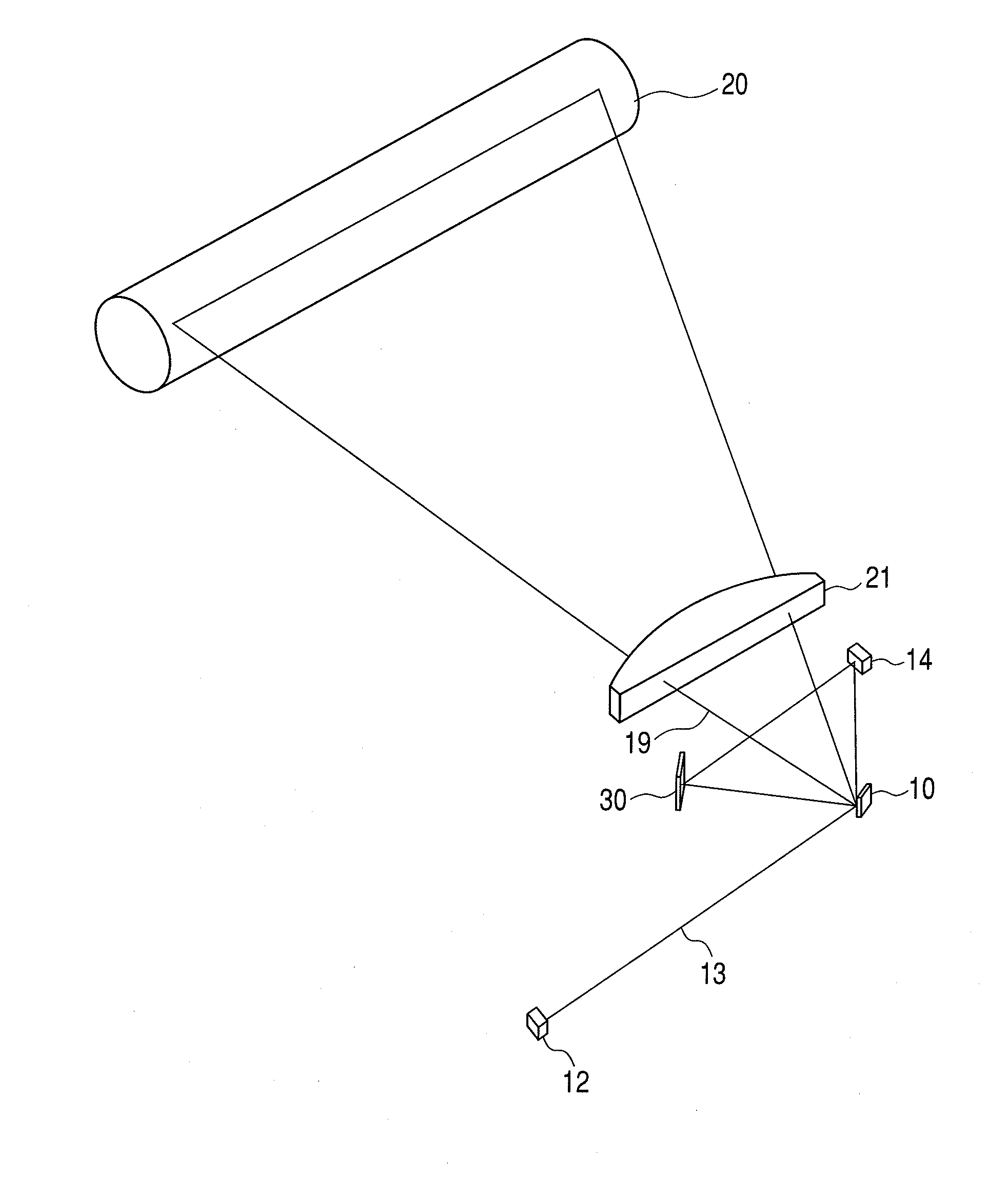
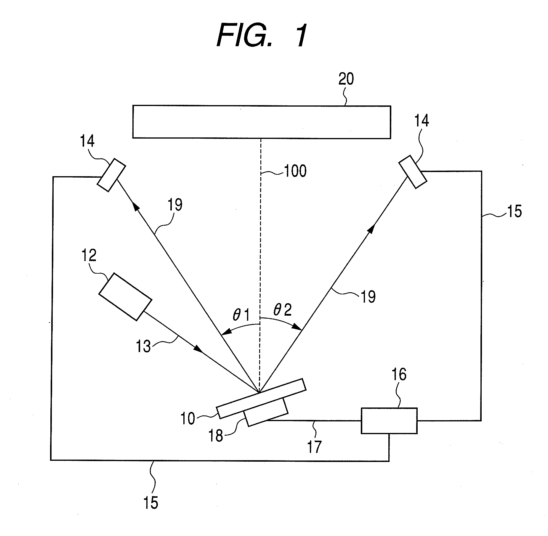
[0068]A method of correcting the offset by observing the clock times when scanning light 19 passes θ1 and θ2 by means of the arrangement of FIG. 1 with two light receiving elements 14 will be described. In this instance, the deflection angle θ of the light deflector 10 is expressed by the above-described formula (2) when the offset is equal to 0. While a drive signal as expressed by the above-described formula (3) is employed, the control parameters of the formula (2) are adopted as the control parameters of the formula (3) because the latter formula corresponds to the expression of the formula (2).
[0069]The following values that are obtained when control parameter X that includes one of A1, A2 and ø of the drive signal of the ligh...
PUM
 Abstract
Description
Claims
Application Information
 - R&D
- Intellectual Property
- Life Sciences
- Materials
- Tech Scout
- Unparalleled Data Quality
- Higher Quality Content
- 60% Fewer Hallucinations
Browse by: Latest US Patents, China's latest patents, Technical Efficacy Thesaurus, Application Domain, Technology Topic, Popular Technical Reports.
© 2025 PatSnap. All rights reserved.Legal|Privacy policy|Modern Slavery Act Transparency Statement|Sitemap|About US| Contact US: help@patsnap.com


