Projector

a projector and projector technology, applied in the field of projectors, can solve the problems of large amount of cost and high design difficulty, and achieve the effect of easy display and convenient display

Inactive Publication Date: 2008-05-29
SEIKO EPSON CORP
View PDF11 Cites 34 Cited by
  • Summary
  • Abstract
  • Description
  • Claims
  • Application Information

AI Technical Summary

Benefits of technology

[0007]An advantage of some aspects of the present invention is to provide a projector capable of easily adjusting the screen size in performing the close-up projection.
[0009]By moving the projection engine section to vary the projection distance, the adjustment of the screen size can be performed. By moving the projection engine section inside the housing, relocation of the projector which has once been installed can be eliminated. Therefore, both of the permanent fixing of the projector and the zoom function can be realized. In particular, in the case of using the ultra short focus optical system, the screen size can dramatically be changed even by such a movement of the projection engine section as allowed with the normal sized housing. Regarding the optical system of the projection engine section, by eliminating the need for incorporating the zoom function into the design of the optical system, the zoom function can easily be realized without increasing difficulty in designing the optical system and complexity of the configuration of the optical system. Since it is only required to make the projection engine section movable, a configuration which can easily be designed can be adopted, thus reduction in the manufacturing cost becomes possible. Further, a highly reliable zoom mechanism with a high accuracy can be realized with a simple configuration. Thus, the projector capable of easily adjusting the screen size in the case of performing close-up projection can be obtained.
[0010]Further, in a preferable aspect of the invention, the image forming section preferably includes an angle widening reflection section for making light wide-angle by reflection. Thus, the dramatic angle widening of the light becomes possible to obtain the configuration capable of performing the close-up projection.
[0015]Further, in another preferable aspect of the invention, at least one of the optical elements disposed closer to the angle widening reflection section is preferably movable. Thus, the focus adjustment can be performed with the simple configuration which can easily be designed.
[0017]Further, in another preferable aspect of the invention, the image forming section preferably includes a spatial light modulation device for modulating the light from the light source in accordance with the image signal. In the case in which the light from the light source section is modulated by the spatial light modulation device, the light source section needs only to emit a predetermined amount of light, and do not need to adjust the amount of light in accordance with the image signal. Thus, an image can easily be displayed on the irradiated surface.
[0018]Further, in another preferable aspect of the invention, the light source section preferably emits a laser beam, and the image forming section preferably includes a scanning section for scanning the laser beam from the light source, thereby displaying an image on the irradiated surface. In the case in which an image is displayed on the irradiated surface by scanning the laser beam from the light source section by the scanning section, although the light source section needs to be adjusted in accordance with the image signal, the image can be displayed without using the projection lens. Thus, an image can easily be displayed on the irradiated surface.

Problems solved by technology

In particular, in the case of a small room, projection of a large screen becomes difficult.
A large amount of cost should be required for making the light wide-angle by only light transmissive optical elements such as lenses.
In the case of the ultra short focus optical system having such a configuration as proposed in the Document 1, very high difficulty level of design is required only for achieving the dramatically wide-angle light.
Therefore, such design as to add the zoom function to the configuration of making the dramatically wide-angle light possible becomes extremely difficult.
Even if the design for incorporating the zoom function is possible, it results in a complicated configuration and steep increase in the cost thereof.
The configuration requiring the body of the projector to be displaced every time the screen size is adjusted is inconvenient, and moreover, places a restriction in permanent installation of the projector.
As described above, in the related art, there is a problem that it is difficult to realize the configuration capable of both the close-up projection and the easy adjustment of the screen size.

Method used


Image

  • Projector
  • Projector
  • Projector

Examples


first embodiment

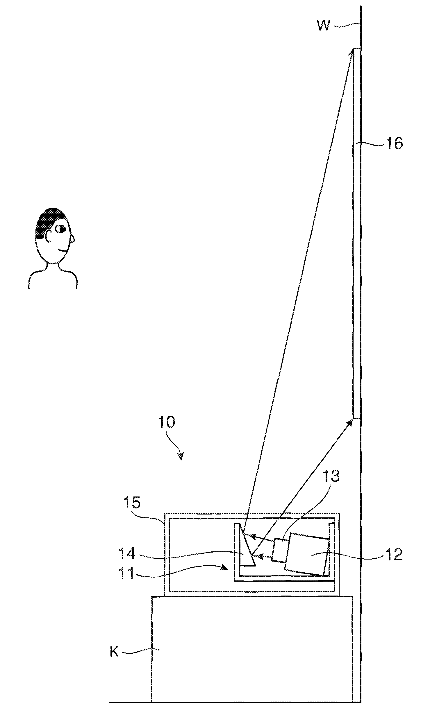
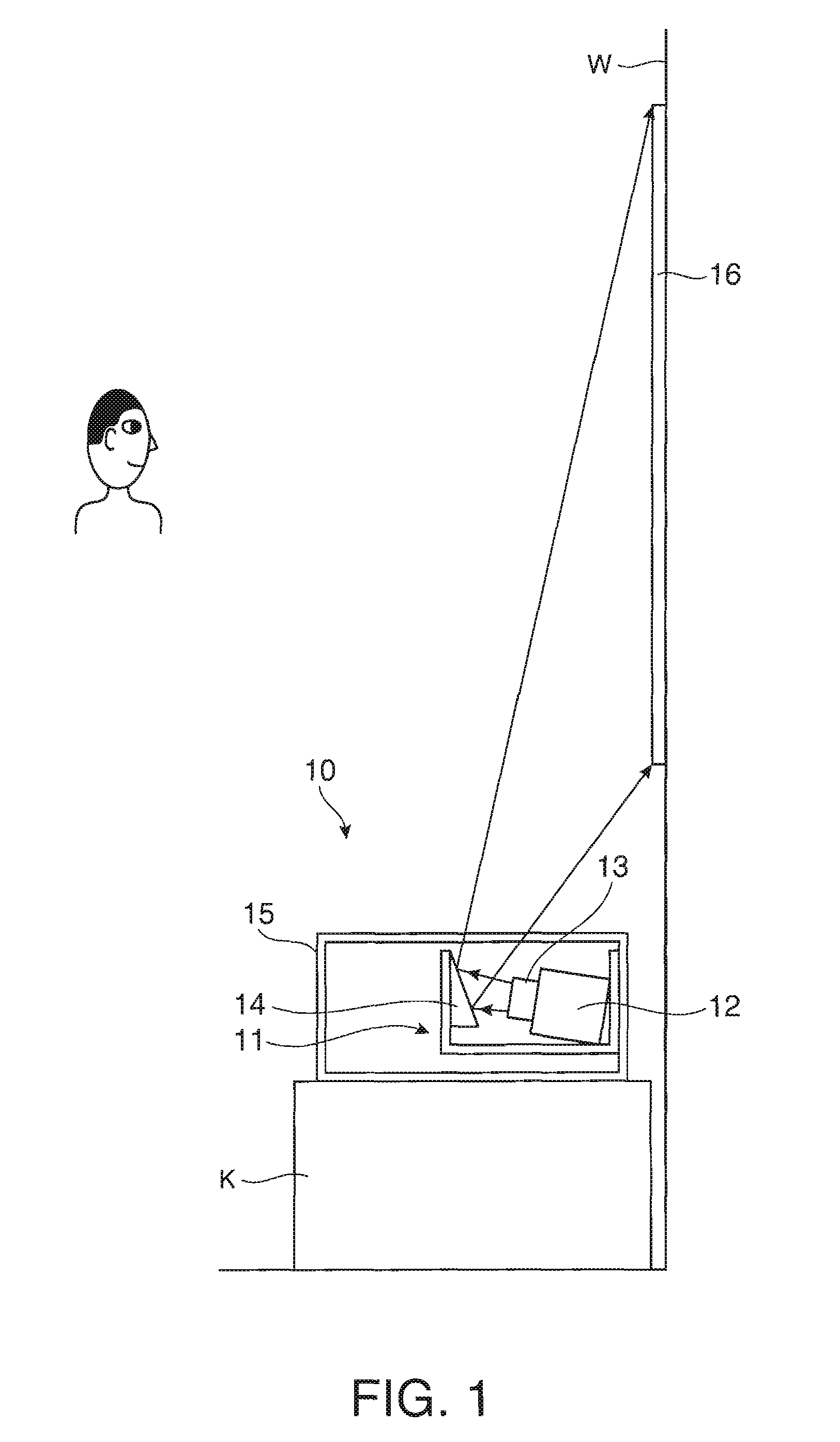
[0031]FIG. 1 shows a schematic configuration of a projector 10 according to a first embodiment of the invention. The projector 10 is a front projection projector for projecting light corresponding to an image signal. The projector 10 performs close-up projection from a position close to an irradiated surface, for example, a position about several tens of centimeters distant from a wall surface W on which a screen 16 is disposed. The projector 10 is provided with a projection engine section 11. The projection engine section 11 projects the light modulated in accordance with the image signal to the screen 16 as the irradiated surface. The project ion engine section 11, is provided with an optical engine 12, a projection lens 13, and an aspherical mirror 14. The optical engine 12, the projection lens 13, and the aspherical mirror 14 are housed in the projection engine section 11, and are configured to be moved integrally by moving the projection engine section 11.

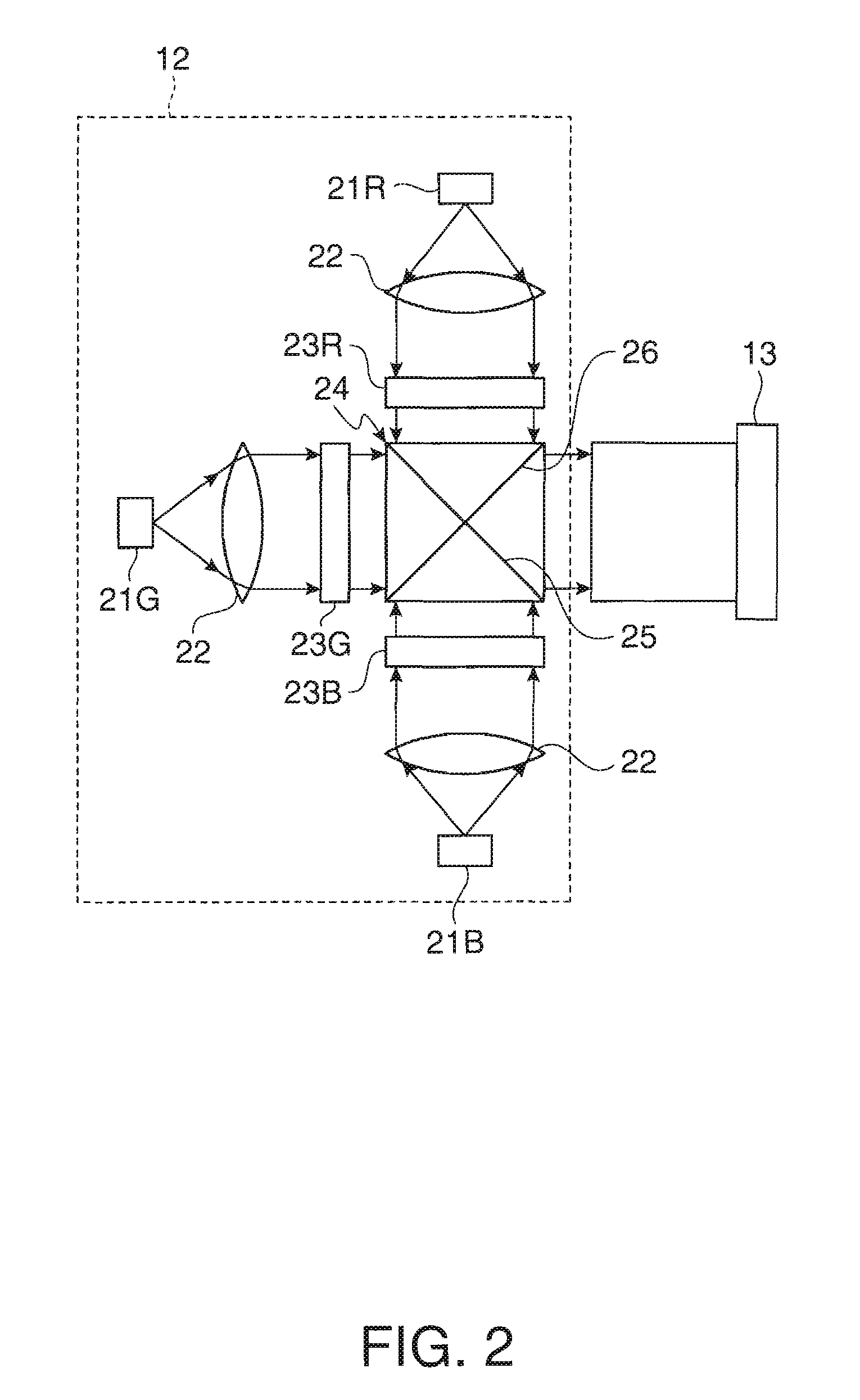
[0032]FIG. 2 shows a s...

second embodiment

[0062]FIG. 10 shows a schematic configuration of a projection engine section 40 according to a second embodiment of the invention. The projection engine section 40 can be applied to the projector 10 (see FIG. 1) described above. The projection engine section 40 of the present embodiment is characterized in including four aspherical mirrors 41, 42, 43, and 44. The same parts as in the first embodiment are denoted with the same reference numerals, and the duplicated explanations will be omitted. The aspherical mirrors 41, 42, 43, and 44 are each a mirror having a curved surface of an aspheric shape. The projection engine section 40 forms a so-called eccentric optical system which has no common optical axis.

[0063]The light from the projection engine section 40 enters the screen not shown after being reflected by each of the aspherical mirrors 41, 42, 43, and 44. The fourth aspherical mirror 44 for reflecting the light passing through the three aspherical mirrors 41, 42, and 43 is the a...


PUM


Abstract

A projector includes a projection engine section including a light source section, an image forming section for displaying an image of a desired size on an irradiated surface using light from the light source section, and projecting light corresponding to an image signal to the irradiated surface, and a housing for housing the projection engine section, wherein the projection engine section is capable of moving in the housing in a direction along a light path.

Description

BACKGROUND[0001]1. Technical Field[0002]The present invention relates to a technical field of a projector, and in particular to a technical field of a projector capable of close-up protection for projecting light from a position near the irradiated surface.[0003]2. Related Art[0004]Most of the projectors which have been in widespread use in the past are placed at positions rather distant from screens in order for assuming an appropriate projection distance. In the case in which the projector is placed at a position distant from the screen, it is required to provide a space where no obstacles for blocking the light exist in the light path between the projector and the screen. The larger the display screen becomes, the more remarkable such a restriction in the installation position of the projector becomes. In particular, in the case of a small room, projection of a large screen becomes difficult. Further consideration to preventing intervenient into the light path should also be give...

Claims


Application Information

Patent Timeline
Patent Type & Authority Applications(United States)
IPC IPC(8): G03B21/28G03B21/14
CPCG02B13/16G03B27/70G03B27/68G03B21/28
Inventor MORIKUNI, EIJI
Owner SEIKO EPSON CORP
Why Eureka
Try Eureka