Power saw miter guide

a technology of power saws and guides, which is applied in the field of power saw miter guides, can solve the problems of single notch not being able to properly constrain the blade, the typical miter box cannot and the cutting of a new notch is unlikely to work with a common hand-held power saw. achieve the effect of precise cutting

Inactive Publication Date: 2008-06-05
WILSON KELCE S
View PDF21 Cites 8 Cited by
  • Summary
  • Abstract
  • Description
  • Claims
  • Application Information

AI Technical Summary

Benefits of technology

[0007]Operating a power saw between a pair of parallel guide rails, which engage opposing sides of saw base plate to constrain the motion of the saw to a straight path, allows for precise cuts. A set of two or more fences allows for multiple cutting options. In some embodiments, two fences may engage opposing sides of the object to be cut simultaneously, holding the object more securely with respect to the guide rails than would a single fence. A possible clamping force holding the two fences against the object allows the miter guide to remain fixed relative to the object so that the user's hand may be freed for another task, such as holding the saw with both hands. The clamping force may result from one fence being adjustable, or the fences may be spaced apart to fit snugly over common sizes of pre-cut lumber.
[0008]In some embodiments, non-parallel fences coupled to the guide rails allow for precise cuts at more than just a single angle. One fence may be oriented at an angle between 59 degrees and 91 degrees with respect to the guide rails, and another fence may be oriented at an angle between 29 degrees and 61 degrees with respect to the guide rails. Because the fences are not parallel, they have a closest point on one side of the guide rails. The ends of the fences may be angled so that the end of each fence is parallel to the other fence at the closest point. Some embodiments do not require a cutting surface. That is, unlike a traditional miter box, in which the object to be cut is placed inside the box, embodiments of the invention may be placed on top of the object, with open space below the object.

Problems solved by technology

Further, the cutting edge of the blade only engages the object to be cut and the cutting surface.
A typical miter box will not work with a common hand-held power saw, because the blade will not be held in place by both notches simultaneously when the cutting starts.
Further, because the blade is circular, it will strike the distant fence and likely cut a new notch in it.
For example, if an object to be cut is placed in a typical miter box, the power saw blade is set in one the notch of the first fence, and the saw is turned on, the single notch is unlikely to properly constrain the blade.
The miter box will become damaged, and will not have achieved its purpose.
Unfortunately, power miter saws may be expensive and heavy, and are often unsuited for some of the tasks for which a power saw is commonly used.
This duplication of power saws can be expensive and burdensome to transport to a job site.

Method used


Image

  • Power saw miter guide
  • Power saw miter guide
  • Power saw miter guide

Examples


Embodiment Construction

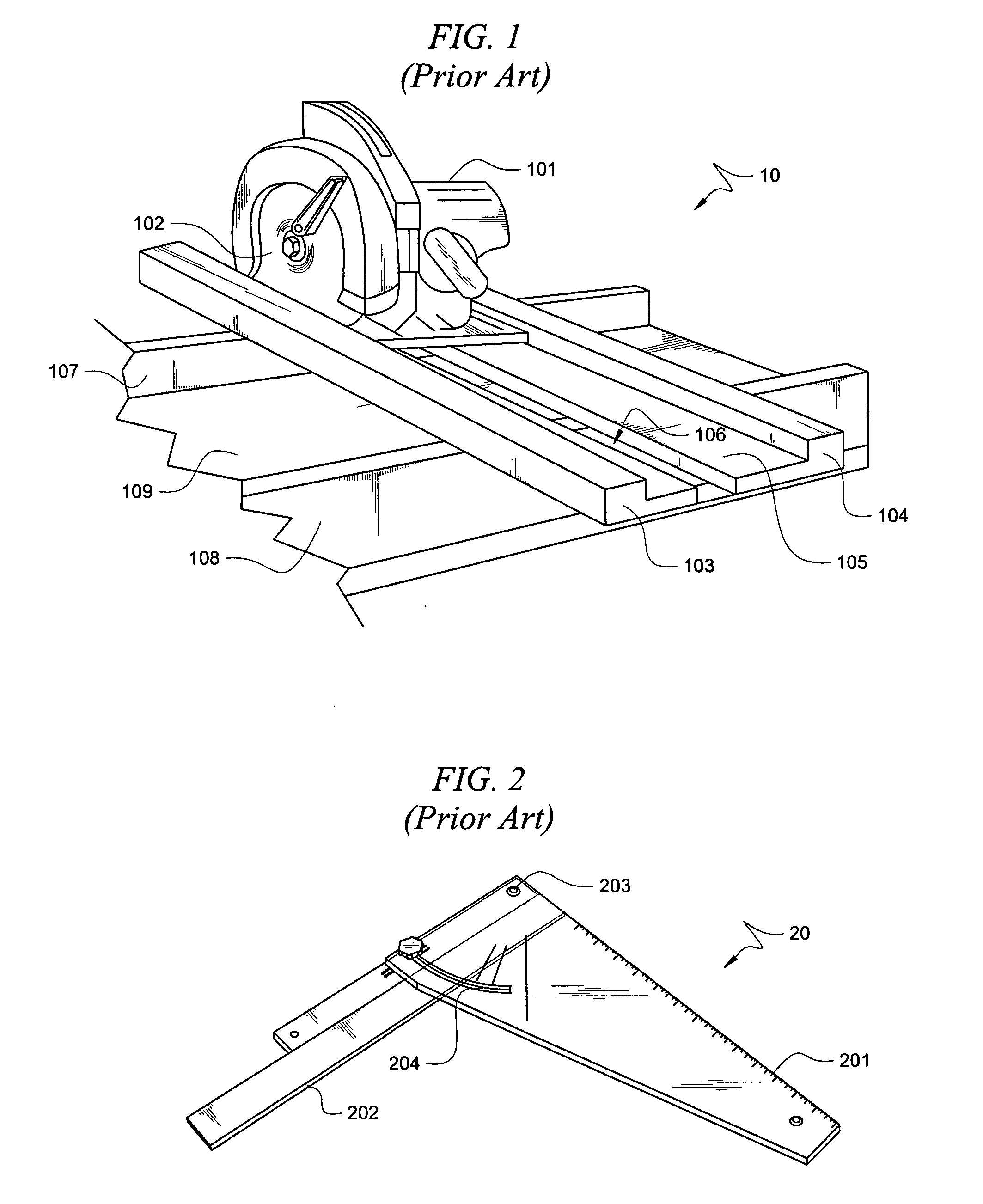
[0019]FIG. 1 shows prior art cutting guide 10 for making 90-degree cross cuts with power saw 101. Prior art cutting guide comprises guide rail 103 and 104, saw support surface 105, parallel fences 107 and 108, and cutting surface 109. Saw support surface 105 comprises notch 106 through which saw blade 102 passes when cutting an object. Because notch 106 completely separates saw support surface 105 into two pieces, each of guide rails 103 and 104 must be firmly attached to both fences 107 and 108 for structural rigidity. As a result, in the prior art device 10, fences 107 and 108 are not adjustable.

[0020]In operation, a user places an object to be cut on cutting surface 109, between fences 107 and 105, completely to the side of one of guide rails 104 and 103. The object is then slid along cutting surface 109 until the part of the object to be cut is beneath notch 106. Since the object must be able to slide along cutting surface 109, and fences 107 and 108 are not adjustable, fences 1...


PUM

PropertyMeasurementUnit
angleaaaaaaaaaa
angleaaaaaaaaaa
angleaaaaaaaaaa

Abstract

Operating a power saw between a pair of parallel guide rails, which engage opposing sides of saw base plate to constrain the motion of the saw to a straight path, allows for precise cuts. A set of two or more fences allows for multiple cutting options. In some embodiments, non-parallel fences coupled to the guide rails allow for precise cuts at more than just a single angle. In some embodiments, two fences may engage opposing sides of the object to be cut simultaneously, holding the object more securely with respect to the guide rails than would a single fence. A possible clamping force holding the two fences against the object allows the miter guide to remain fixed relative to the object so that the user's hand may be freed for another task, such as holding the saw with both hands.

Description

TECHNICAL FIELD[0001]The invention relates generally to woodworking and industrial power tools, and more particularly, to providing a cutting guide for a hand-held power saw.BACKGROUND[0002]Miter boxes are cutting guides that allow precision cuts using hand-held saws, because they both constrain the saw to move in a straight line and also align the cutting path with respect to the object being cut. Typical miter boxes are designed for hand-operated saws, and include cutting guides for 90-degree cross cuts, as well as 45-degree miter cuts. The cutting guides in a typical miter box are usually pairs of notches on opposing sides of the box, barely wider than the saw blade, and which are oriented at a precise angle with respect to the box's inner surfaces. These surfaces are a cutting surface, which the blade will score as it cuts through the object, and at least one other alignment surface, which may be identified as a fence. A miter box typically forms a 3-sided trough with a cutting ...

Claims


Application Information

Patent Timeline
Patent Type & Authority Applications(United States)
IPC IPC(8): B27G5/02
CPCB23D47/02B27B9/04B27B27/06Y10T83/7627Y10T83/7697Y10T83/8889Y10T83/68Y10T83/04Y10T83/8763Y10T83/7613Y10T83/8878Y10T83/8773Y10T83/6609
Inventor WILSON, KELCE S.
Owner WILSON KELCE S
Why Eureka
Try Eureka