Apparatus and method for controlling optical power and extinction ratio

Inactive Publication Date: 2008-06-05
RAYBIT SYST
View PDF3 Cites 23 Cited by
  • Summary
  • Abstract
  • Description
  • Claims
  • Application Information

AI Technical Summary

Benefits of technology

[0016]The present invention has been made in another effort to provide a device and a method for automatically sensing a change of the optical output/current characteristic curve caused by temperature change and aging when a de

Problems solved by technology

The reduction of the extinction ratio influences the power penalty in the optical communication to reduce the maximum transmission distance.
Also, there are many restrictions to changing the lookup table, the data of which are statistically processed so as to acquire the desired extinction ratio when considering the costs caused by measurement and control, and time.
Therefore, the problem is that the lookup table is only applied to the laser diodes having characteristic values of a similar optical output/current characteristic curve.
However in the above-noted second method, a circuit for applying the pilot tone signal is added so that the whole circuit structure becomes more complicated and jitter caused by applying the pilot

Method used


Image

  • Apparatus and method for controlling optical power and extinction ratio
  • Apparatus and method for controlling optical power and extinction ratio
  • Apparatus and method for controlling optical power and extinction ratio

Examples


first embodiment

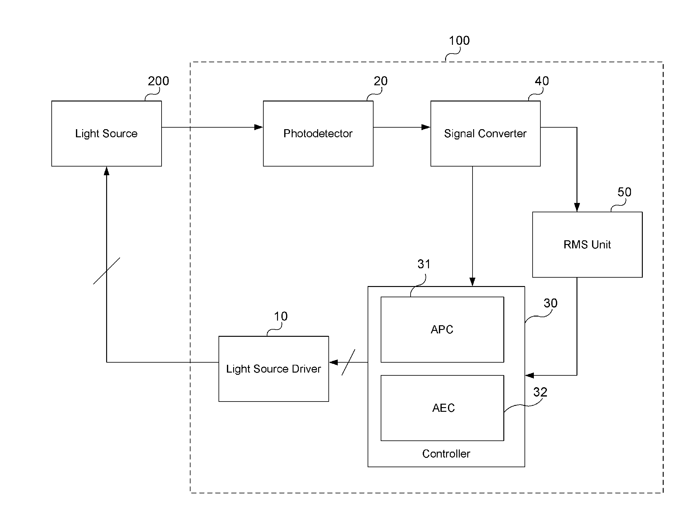
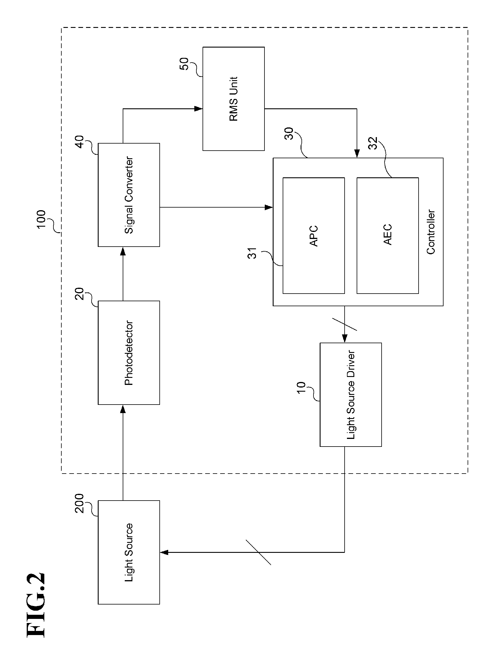
[0028]FIG. 2 shows a configuration diagram for an optical power and extinction ratio control device according to the present invention. For better comprehension and ease of description, the optical power and extinction ratio control device according to the embodiment of the present invention will be referred to as an optical control device.

[0029]An optical control device 100 controls the current applied to a light source 200 based on the light output by the light source 200 so as to maintain the optical power and extinction ratio, as shown in FIG. 2.

[0030]For this purpose, the optical control device 100 includes a light source driver 10 for supplying a current to the light source 200, a photodetector 20 for detecting the light output by the light source 200 and outputting a corresponding electrical signal, a controller 30 for controlling the light source driver 10 based on the detected light, and a signal converter 40 for converting the signal output by the photodetector into a sign...

second embodiment

[0053]An optical control device according to the present invention will now be described.

[0054]It is described in the first embodiment that the optical power output by the light source and the extinction ratio are controlled when the light source is operated by the supplied modulation current to output corresponding light, and it will be described in the second embodiment that the optical power and the extinction ratio are controlled by connecting a means for modulating the light to an output terminal of the light source when the light output by the light source is modulated and output. The means, connected to the output terminal of the light source, for modulating the output light will be referred to as an external modulator.

[0055]FIG. 5 shows a configuration diagram for an optical control device according to a second embodiment of the present invention. The constituent elements performing the same functions as those of the first embodiment have the same reference numerals as in th...


PUM


Abstract

The present invention relates to an optical power and extinction ratio controlling device and method. An optical signal output from a light source is detected and optical power and extinction ratio of the light source are controlled. In detail, a feedback signal is provided to the light source to automatically control the bias current based on a DC signal output by a photodetector detecting the optical signal. Therefore, the optical output of the light source is maintained. Also, an optical signal output by the photodetector is converted into a predetermined times DC signal, and a feedback signal is provided to the light source to automatically control the modulation current based on the DC signal. Therefore, the extinction ratio of the light source is maintained. As a result, the extinction ratio is automatically maintained to satisfy the change of condition and the characteristic of light source, thereby maintaining quality optical outputs.

Description

BACKGROUND OF THE INVENTION[0001](a) Field of the Invention[0002]The present invention relates to an optical controller. More particularly, the present invention relates to a device and method for automatically controlling optical power provided by a light source, and an optical extinction ratio (ER).[0003](b) Description of the Related Art[0004]In a general optical communication network, it is required to maintain outputs and an extinction ratio (an intensity ratio of the minimum transmission light and the maximum transmission light) of a laser diode and an optical transmitter that are determined according to data rates and transmission distances in order to provide quality optical signal transmission. The laser diode generally used as a light source in the optical communication starts being oscillated when a current of more than a threshold current is applied at a predetermined temperature, and the optical output of the laser diode is linearly increased as the applied current valu...

Claims


Application Information

Patent Timeline
IPC IPC(8): G05D25/02H04B10/43
CPCH01S5/0085H01S5/06832H01S5/0683G02B6/00H04B10/50H04B10/564
Inventor LYU, GAP YOULKOO, KILHUNKANG, MIN HEE
Owner RAYBIT SYST
Why Eureka
Try Eureka