Method and Apparatus for Magnetic Field Sensor Calibration

a magnetic field sensor and calibration method technology, applied in the direction of magnetic field magnitude/direction, measurement devices, instruments, etc., can solve the problems of additional magnetic fields and yielding imprecise results, and achieve the effect of more accuracy and more accuracy

Inactive Publication Date: 2008-06-05
YAMCON
View PDF5 Cites 12 Cited by
  • Summary
  • Abstract
  • Description
  • Claims
  • Application Information

AI Technical Summary

Benefits of technology

[0005]The methods and devices described below provide for calibration of multi-axis sensors such as two or three-axis magnetic field sensors with an artificial magnetic calibration field, or a sequence of magnetic calibration fields, that overwhelm the earth's magnetic field and any other extraneous magnetic fields that may be present in the calibration area. The calibration field or fields are produced with a known relationship to the test stand or jig on which a two and or three-axis magnetic field sensor is secured. The calibration fields are oriented to produce fields that have generally parallel lines of force (relative to the sensor to be calibrated) with minimal curvature or discontinuity. For each coil or calibration field, data from each sensor may be collected and analyzed to enable one or more correction factors to be determined for each sensor. The correction factors may be provided to the apparatus in which the magnetic sensor is secured to correct sensor data and provide more accuracy.
[0006]In an alternative technique, a single mag

Problems solved by technology

However the presence of structural steel, electrical wiring and motors as in buildings and factories significant

Method used


Image

  • Method and Apparatus for Magnetic Field Sensor Calibration
  • Method and Apparatus for Magnetic Field Sensor Calibration
  • Method and Apparatus for Magnetic Field Sensor Calibration

Examples


Embodiment Construction

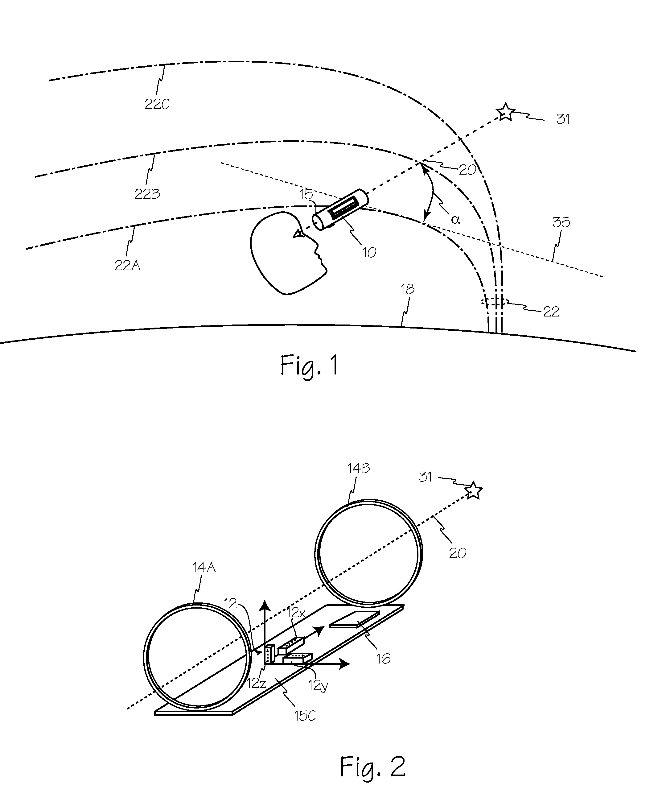
[0010]Celestial object locating device 10 of FIG. 1 includes electronics 15 oriented relative to viewing axis 20. A two or three-axis magnetic field sensor incorporated in electronics 15 may be used to determine one or more angles such as angle α relative to magnetic field 22 of earth 18. At most locations on the earth a user will encounter magnetic field lines of force such as lines 22A, 22B and 22C that are generally parallel.

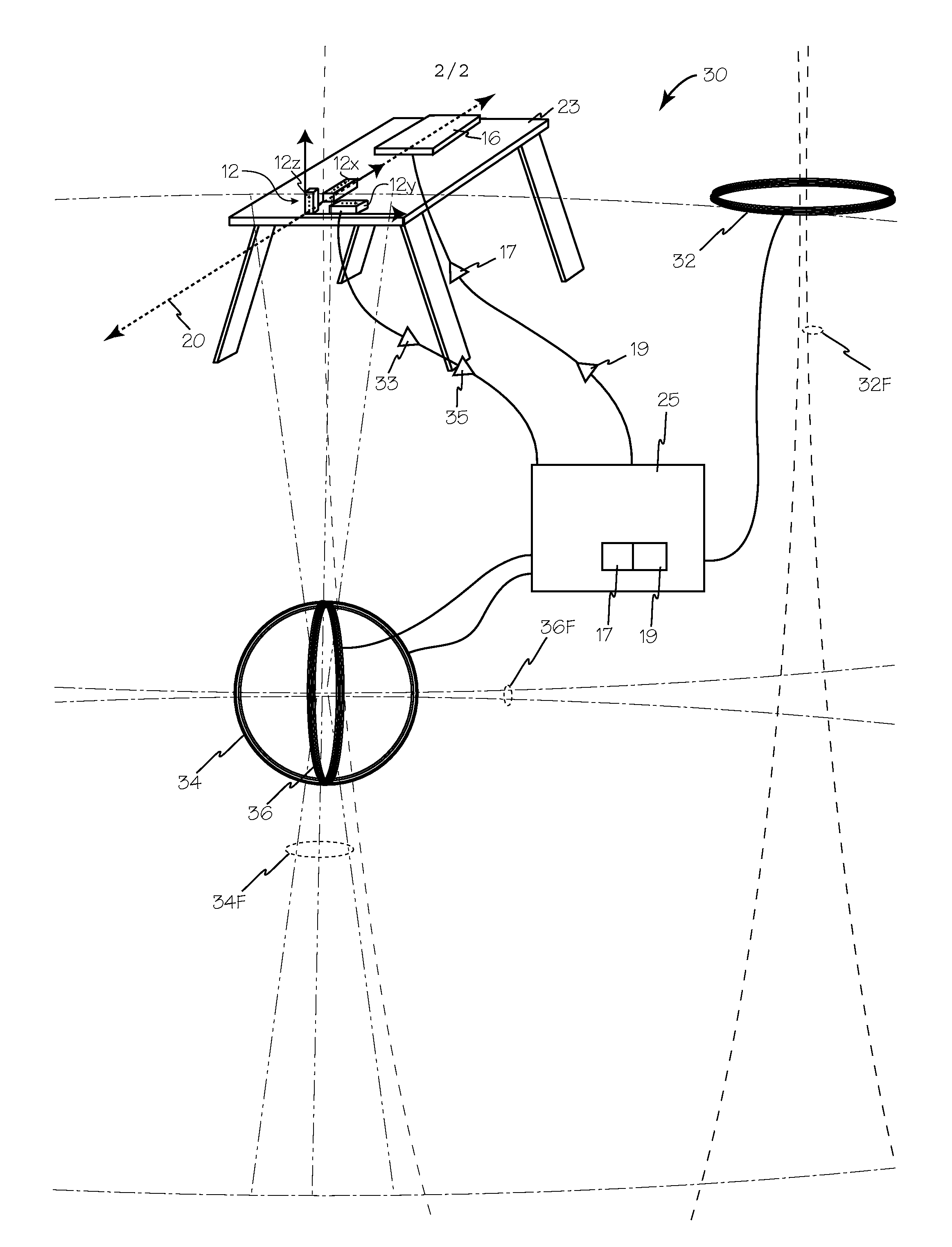
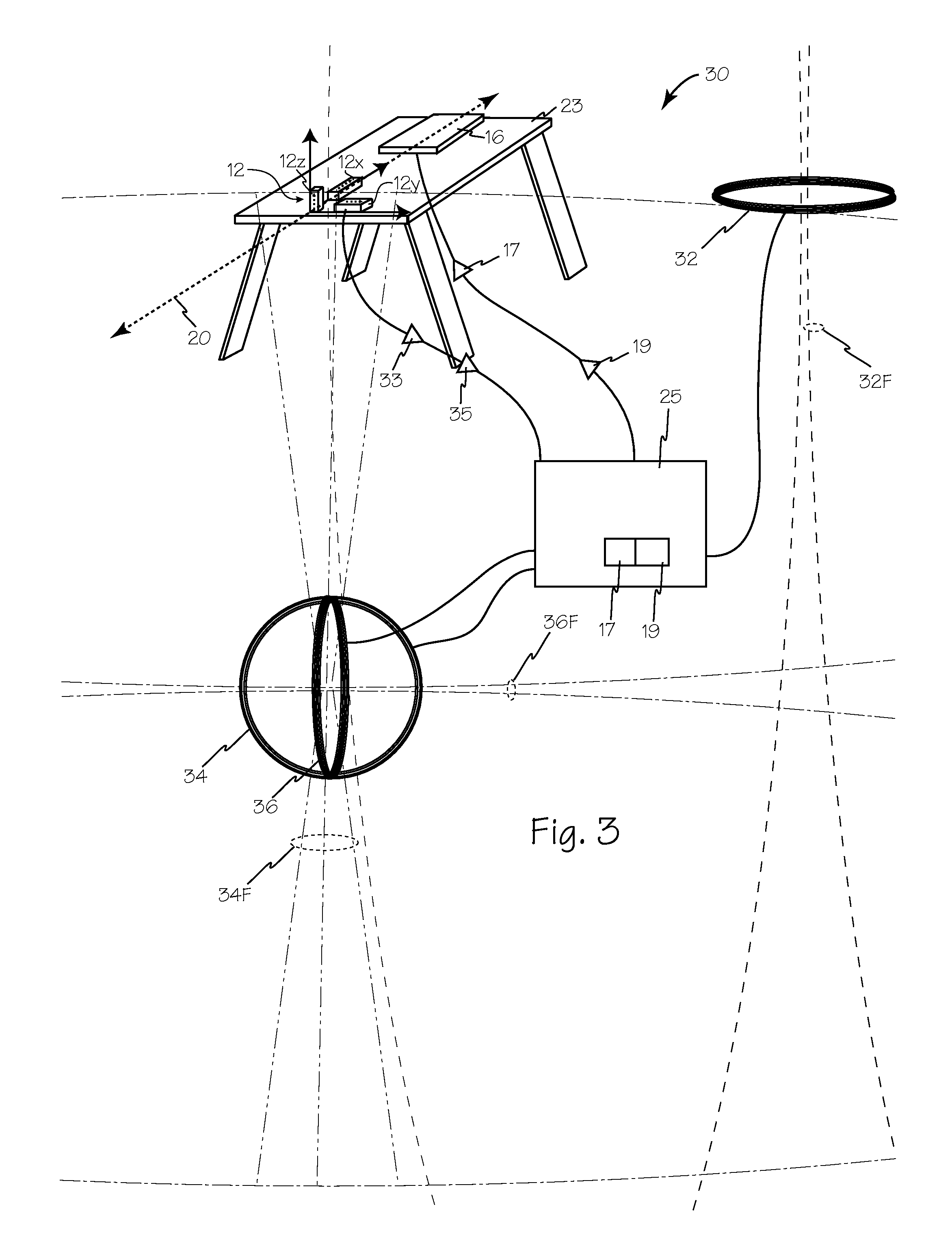
[0011]Electronics 15 may include one or more subassemblies such as board 15C and microprocessor 16 of FIG. 2. Subassembly 15C may include a two or three-axis magnetic field sensor such as three-axis sensor 12. Sensor 12 includes three sub-elements 12X, 12Y and 12Z. The orientation of each sub-element to the other sub-elements and to the viewing axis may be calibrated and offset parameters determined for each sub-assembly.

[0012]Calibration system 30 of FIG. 3 includes test stand 23 and field generators 32, 34 and 36 which generate magnetic calibration fields 3...


PUM


Abstract

The methods and devices provide for calibration of two or three-axis magnetic field sensors with an artificial magnetic calibration field, or a sequence of magnetic calibration fields, that overwhelm the earth's magnetic field and any other extraneous magnetic fields that may be present in the calibration area. The calibration field or fields are produced with a known relationship to a test stand or jig on which a two and or three-axis magnetic field sensor is secured. The calibration fields are oriented to produce fields that have generally parallel lines of force (relative to the sensor to be calibrated) with minimal curvature or discontinuity. For each coil or calibration field, data from each sensor may be collected and analyzed to enable one or more correction factors to be determined for each sensor. The correction factors may be provided to the apparatus in which the magnetic sensor is secured to correct sensor data and provide more accuracy.

Description

RELATED APPLICATIONS[0001]This application claims priority from copending U.S. patent application Ser. No. 11 / 607,293 filed Nov. 30, 2006.FIELD OF THE INVENTIONS[0002]The inventions described below relate to the field of magnetic sensor calibration, and more specifically to methods and apparatus for calibrating two-axis and or three-axis magnetic field sensors for use in celestial object locators.BACKGROUND OF THE INVENTIONS[0003]Calibration of magnetic field sensors intended for detection of the magnetic field of the earth may be performed using the earth's magnetic field as a reference. However the presence of structural steel, electrical wiring and motors as in buildings and factories significantly disrupts the earth's magnetic field, and may generate additional magnetic fields and yield imprecise results.[0004]What is needed are methods and apparatus for producing one or more stable and predictable magnetic fields that may be used to calibrate two and or three-axis magnetic fiel...

Claims


Application Information

Patent Timeline
IPC IPC(8): G01R35/00
CPCG01R33/0206
Inventor LEMP, MICHAEL
Owner YAMCON
Why Eureka
Try Eureka