Antenna array including a phase shifter array controller and algorithm for steering the array

a phase shifter array and controller technology, applied in the field of lowbit phase shifter phased array antennas, can solve the problems ofperiodic phase modulation giving inferior performance, and achieve the effect of preventing the production of any grating lobes and preventing production

Active Publication Date: 2008-06-05
THE BOEING CO
View PDF5 Cites 27 Cited by
  • Summary
  • Abstract
  • Description
  • Claims
  • Application Information

AI Technical Summary

Benefits of technology

[0008]In accordance with another embodiment of the present invention, a method to steer an electronically steerable antenna array may include associating a phase shifter with each radiating element of the antenna array. The method may also include providing a progressive phase delay to each radiating element to produce an electromagnetic wave propagating in a desired direction and to substantially prevent production of any undesirable lobes, such as grating lobes, high side lobes or the like, in a radiation pattern ...

Problems solved by technology

However, this periodic phase modulation gives inferior performance because of high side lobes in the radiation pattern and other anomalies due to the accumulati...

Method used


Image

  • Antenna array including a phase shifter array controller and algorithm for steering the array
  • Antenna array including a phase shifter array controller and algorithm for steering the array
  • Antenna array including a phase shifter array controller and algorithm for steering the array

Examples


Embodiment Construction

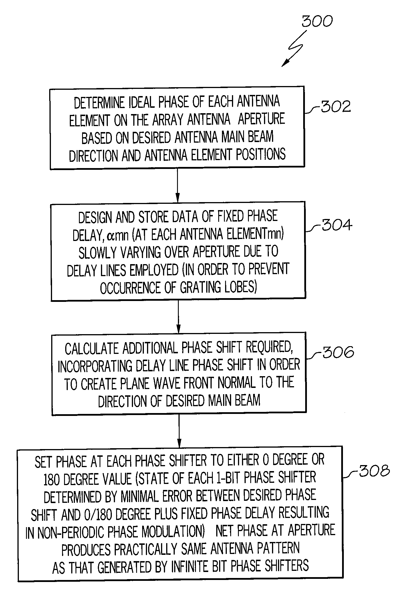
[0016]The following detailed description of embodiments refers to the accompanying drawings, which illustrate specific embodiments of the invention. Other embodiments having different structures and operations do not depart from the scope of the present invention.

[0017]As will be appreciated by one of skill in the art, the present invention may be embodied as a method, system, or computer program product. Accordingly, portions of the present invention may take the form of an entirely hardware embodiment, an entirely software embodiment (including firmware, resident software, micro-code, etc.) or an embodiment combining software and hardware aspects that may all generally be referred to herein as a “circuit,”“module” or “system.”

[0018]The present invention is described below with reference to flowchart illustrations and / or block diagrams of methods, apparatus (systems) and computer program products according to embodiments of the invention. It will be understood that each block of th...


PUM


Abstract

An antenna system may include an antenna array which includes a plurality of radiating elements. The system may also include a phase shifter controller and algorithm to apply a non-periodic modulation to an excitation of each radiating element.

Description

BACKGROUND OF THE INVENTION[0001]The present invention relates to antennas, antenna arrays and the like, and more particularly to a low-bit phase shifter phased array antenna including a phase shifter controller and algorithm adapted for steering or pointing a beam from the array in a desired direction.[0002]Currently, antenna arrays with densely placed elements, for example arrays with spacing approximately 0.1 wavelengths between elements, treat the array as analogous to a phase grating. In this approach phase shifter settings are determined by an optical grating equation for each row of the array with a phase modulation period, Λ, given by equation 1:Λ=λn-sin(θo)(1)[0003]Where λ is the frequency wavelength, n is the square of the relative dielectric constant of the feeding line (in an optical implementation, this would be the index of refraction of the lens material), and θo is the desired scan angle. The phase shifter settings are then set to achieve a square-wave phase modulati...

Claims


Application Information

Patent Timeline
IPC IPC(8): H01Q3/36
CPCH01Q3/385H01Q3/38H01Q3/46H01Q15/06H01Q21/0018
Inventor CHOI, CHANG W.KEITH, ALAN R.WALLOCH, WESLEY F.
Owner THE BOEING CO
Why Eureka
Try Eureka