Inkjet Print Cartridge

Inactive Publication Date: 2008-06-05
HEWLETT PACKARD DEV CO LP
View PDF9 Cites 6 Cited by
  • Summary
  • Abstract
  • Description
  • Claims
  • Application Information

AI Technical Summary

Benefits of technology

[0010]The invention avoids the need for a flexible printed circuit, and allows a printhead, for example of the kind described in our copending British p

Problems solved by technology

Rework of the assembly is therefore very difficult.

Method used


Image

  • Inkjet Print Cartridge
  • Inkjet Print Cartridge
  • Inkjet Print Cartridge

Examples


first embodiment

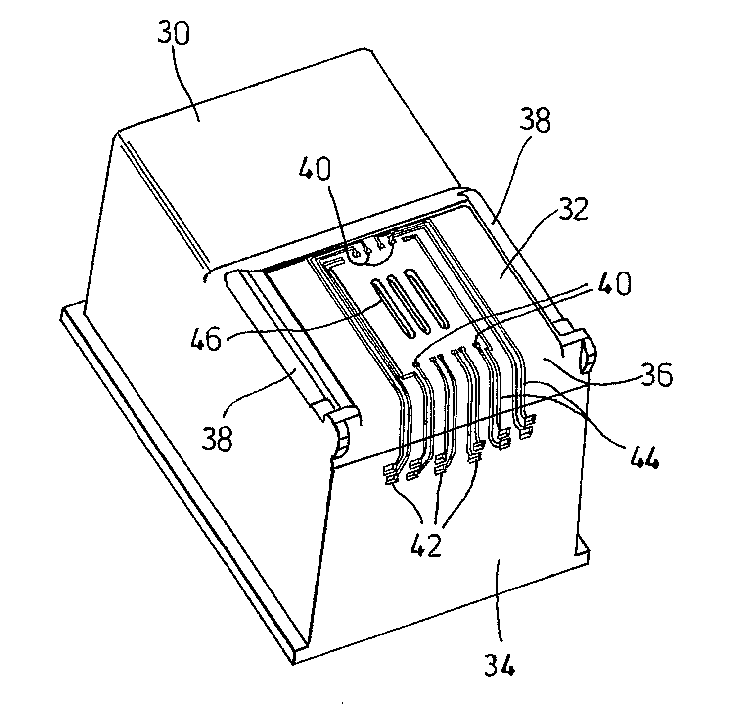
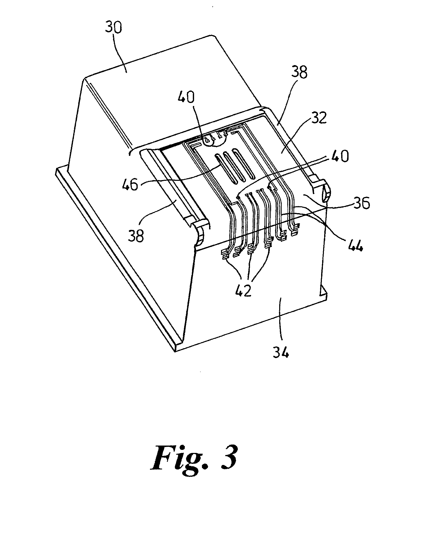
[0023]In the method the next step comprises placing a stencil 50, FIG. 5, in intimate contact with the flat surface portion 32 of the cartridge body 30 between the ridges 38. The stencil 50 has a pattern of openings 52 corresponding to and in register with the terminal regions 40 and those parts of the channels 44 in the flat surface portion 32 and around the radiused edge 36. However, the stencil has no openings corresponding to the ink delivery slots 46, which are therefore blocked off.

[0024]Next, FIG. 6, a conductive paste is applied as a bead 54 in front of an elastomeric squeegee blade 56. The volume of paste dispensed is approximately twice the volume of the terminal regions 40 and the parts of the channels 44 to be filled. Starting from a position at the far end of the stencil 50 to the radiused edge 36, the squeegee 56 is advanced towards the radiused edge (i.e. in the direction of the arrow) forcing the conductive paste 54 through the stencil openings 52 into the terminal ...

second embodiment

[0033]In the invention, instead of screen printing a conductive material into the recessed terminal regions 40, 42 and channels 44 of the moulded cartridge body 30, a suspension of palladium metal catalyst is inkjet printed into the terminal regions and channels and, after drying, is electrolessly plated with copper.

[0034]Thus, FIGS. 13 and 14, an inkjet printhead 80 is aligned to the cartridge body 30 using machine vision. The printhead 80 then scans the body 30 in a plurality of swathes and ejects ink selectively in a pattern that deposits palladium metal suspension 82 in the recessed terminal regions 40, 42 and channels 44. The printhead 80 is moved incrementally after each print swathe so that the palladium suspension is deposited in all the terminal regions 40, 42 and along the entire length of the channels 44, the body 30 being rotated when the printhead 80 is at the radiused edge 36 to ensure that deposition occurs continuously along the channels. The drop size of the suspens...


PUM


Abstract

A method of making an inkjet print cartridge comprises forming a cartridge body (30) and applying directly to the surface of the body first and second sets of electrical terminals (40a, 42a) selectively connected by conductive tracks (44). A printhead (68) is mounted to the body (30) in electrical connection with the first set of terminals (40a). The second set of terminals (42a) is adapted for electrical connection to printer circuitry. The electrical terminals and conductive tracks may be located in corresponding recesses in the cartridge body, being deposited therein by squeegee or inkjet printing.

Description

TECHNICAL FIELD[0001]This invention relates to inkjet print cartridges and methods of making them.BACKGROUND ART[0002]FIG. 1 is a simplified view of a conventional prior art inkjet cartridge. It comprises a moulded plastics cartridge body 10 containing one or more internal ink reservoirs. A printhead 12 is mounted in a recess 14 in the surface of the body 10. As is well known, a typical printhead 12 contains a large number of internal ink ejection elements which can be selectively actuated by printer circuitry via a flexible printed circuit 16 bonded to the surface of the cartridge body. Each time an ink ejection element is actuated, a drop of ink is ejected forcibly through a respective orifice 18 in the exposed (outer) surface of the printhead. The ink is supplied to the printhead via one or more ink supply slots in the underside of the printhead which are in fluid communication with the ink reservoirs) via respective apertures in the cartridge body 10.[0003]The flexible printed c...

Claims


Application Information

Patent Timeline
IPC IPC(8): B41J2/175
CPCB41J2/17559B41J2/1753B41J2/17503
Inventor MCCABE, DECLAN JOHNANNETT, LAURAKEENAN, PHILIP THOMASBREEN, JOHN
Owner HEWLETT PACKARD DEV CO LP
Why Eureka
Try Eureka