Two-dimensional micro optical scanner

a scanner and micro-optical technology, applied in optics, instruments, electrical equipment, etc., can solve the problems of high driving voltage, high speed driving, high risk of damage to the support axis of the vertical mirror by external impact,

Inactive Publication Date: 2008-06-05
SAMSUNG ELECTRONICS CO LTD
View PDF4 Cites 31 Cited by
  • Summary
  • Abstract
  • Description
  • Claims
  • Application Information

AI Technical Summary

Benefits of technology

[0013]According to another aspect of the present invention, there is provided a two-dimensional micro optical scanner including first and second mirrors formed on the sam...

Problems solved by technology

Such two-dimensional micro optical scanners can be miniaturized, but disadvantageously there is coupling between the horizontal and vertical motions of the mirror, thereby making it difficult to achieve precise control, high speed drivin...

Method used


Image

  • Two-dimensional micro optical scanner
  • Two-dimensional micro optical scanner
  • Two-dimensional micro optical scanner

Examples


Embodiment Construction

[0024]The present invention will now be described more fully with reference to the accompanying drawings, in which exemplary embodiments of the invention are shown.

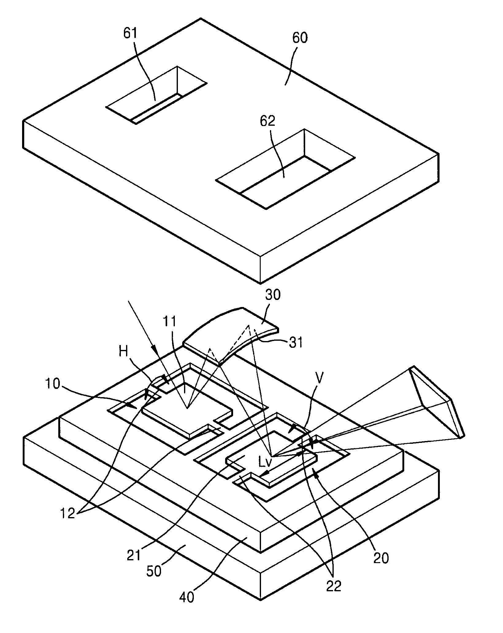
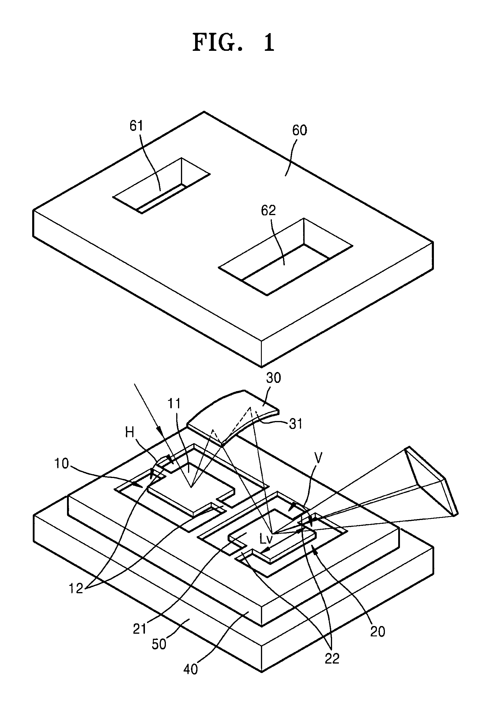
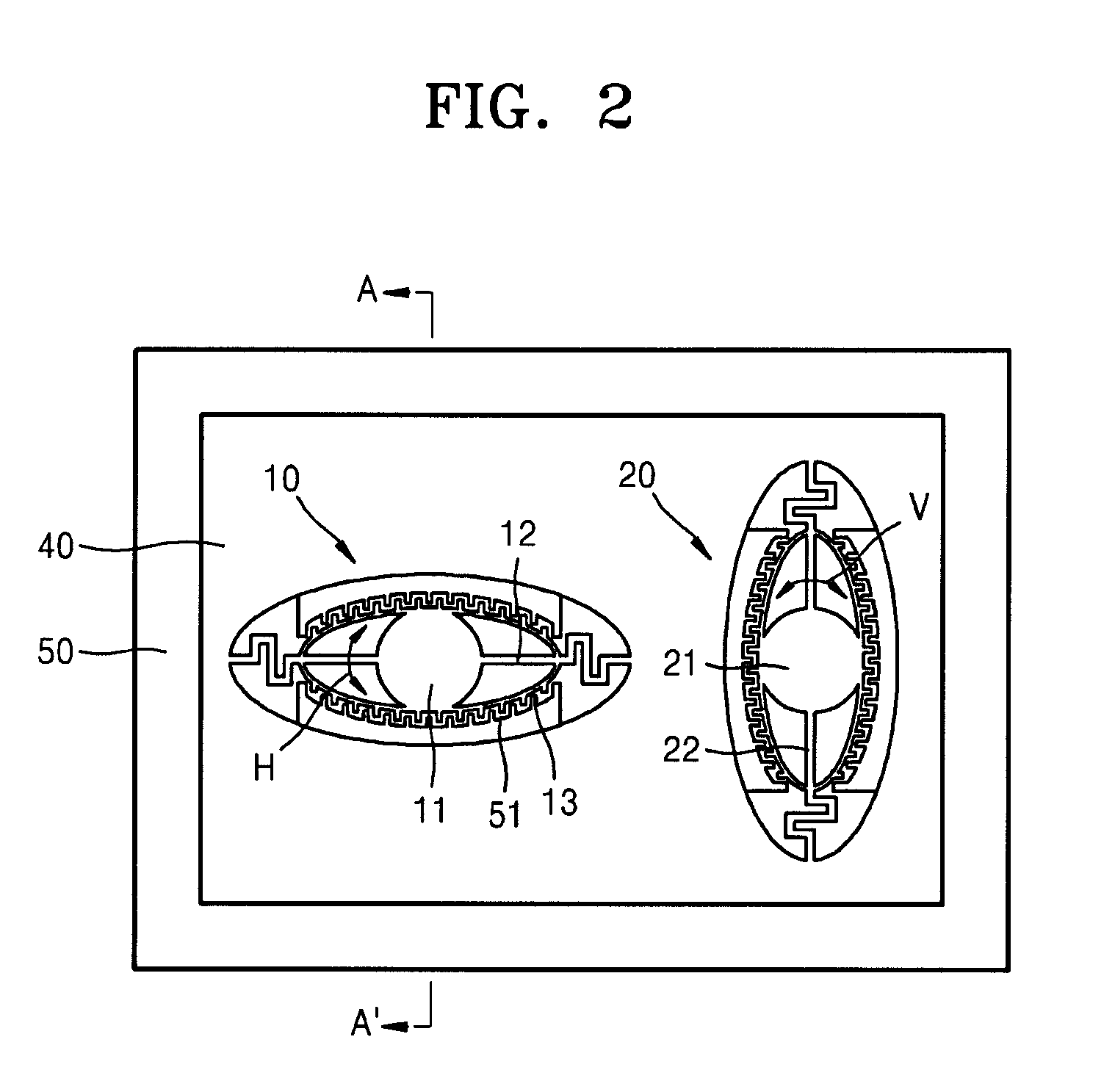
[0025]FIG. 1 is a perspective view of a two-dimensional micro optical scanner according to an exemplary embodiment of the present invention. Referring to FIG. 1, a first scanner 10 includes a first mirror 11 and a first support axis 12. A second scanner 20 includes a second mirror 21 and a second support axis 22. The first mirror 11 is pivoted in a first direction H about the first support axis 12, and the second mirror 21 is pivoted in a second direction V about the second support axis 22. An optical path changing member 30 directs light reflected by the first mirror 21 to the second mirror 21. First and second windows 61 and 62 are formed in an upper cover 60. For example, light L introduced through the first window 61 may be horizontally scanned by the first scanner 10, incident on the second scanner 20 by the optical ...


PUM


Abstract

A two-dimensional micro optical scanner is provided. The two-dimensional micro optical scanner includes a first scanner with a first mirror pivoted in a first direction; a second scanner with a second mirror pivoted in a second direction; and an optical path changing member with a curved mirror. The optical path changing member directs light scanned by the first scanner to the second scanner.

Description

CROSS-REFERENCE TO RELATED PATENT APPLICATION[0001]This application claims priority from Korean Patent Application No. 10-2006-0120977, filed on Dec. 1, 2006 in the Korean Intellectual Property Office, the disclosure of which is incorporated herein in its entirety by reference.BACKGROUND OF THE INVENTION[0002]1. Field of the Invention[0003]Apparatuses consistent with the present invention relate to a micro optical scanner, and more particularly, to a two-dimensional micro optical scanner that scans light in two dimensions by pivoting two mirrors in different directions.[0004]2. Description of the Related Art[0005]Micro optical scanners are widely used in displays, printers, measurement systems, and precision machining using optical scanning. Micro optical scanners include a mirror that reflects light using micro-electro-mechanical system (MEMS) technology, a support axis that supports the mirror, and driving means for pivoting the reflecting mirror.[0006]Two-dimensional micro optica...

Claims


Application Information

Patent Timeline
IPC IPC(8): G02B26/08
CPCG02B26/105G02B26/101G02B26/0833G02B27/0983H04N1/113
Inventor PARK, YONG-HWACHO, JIN-WOO
Owner SAMSUNG ELECTRONICS CO LTD
Why Eureka
Try Eureka