Camera module and imaging apparatus

Active Publication Date: 2008-06-05
MAXELL HLDG LTD
View PDF6 Cites 46 Cited by
  • Summary
  • Abstract
  • Description
  • Claims
  • Application Information

AI Technical Summary

Benefits of technology

[0021]According to the present invention, there is provided a camera module or the like in which it is prevented that the excessive portion of adhesive enters an imaging area when producing, for example, a camera module to ther

Problems solved by technology

In the conventional camera module, an excessive portion of the adhesive enters such gap.
However, since the gap is reduce

Method used


Image

  • Camera module and imaging apparatus
  • Camera module and imaging apparatus
  • Camera module and imaging apparatus

Examples


Embodiment Construction

[0031]Referring now to the accompanying drawings, description will be given in detail of an embodiment according to the present invention.

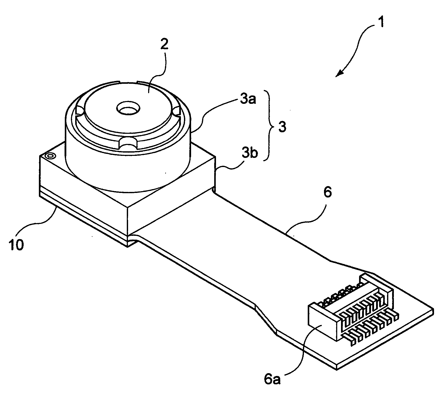
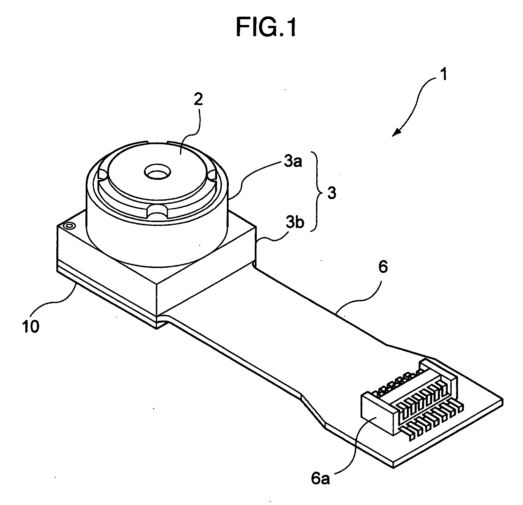
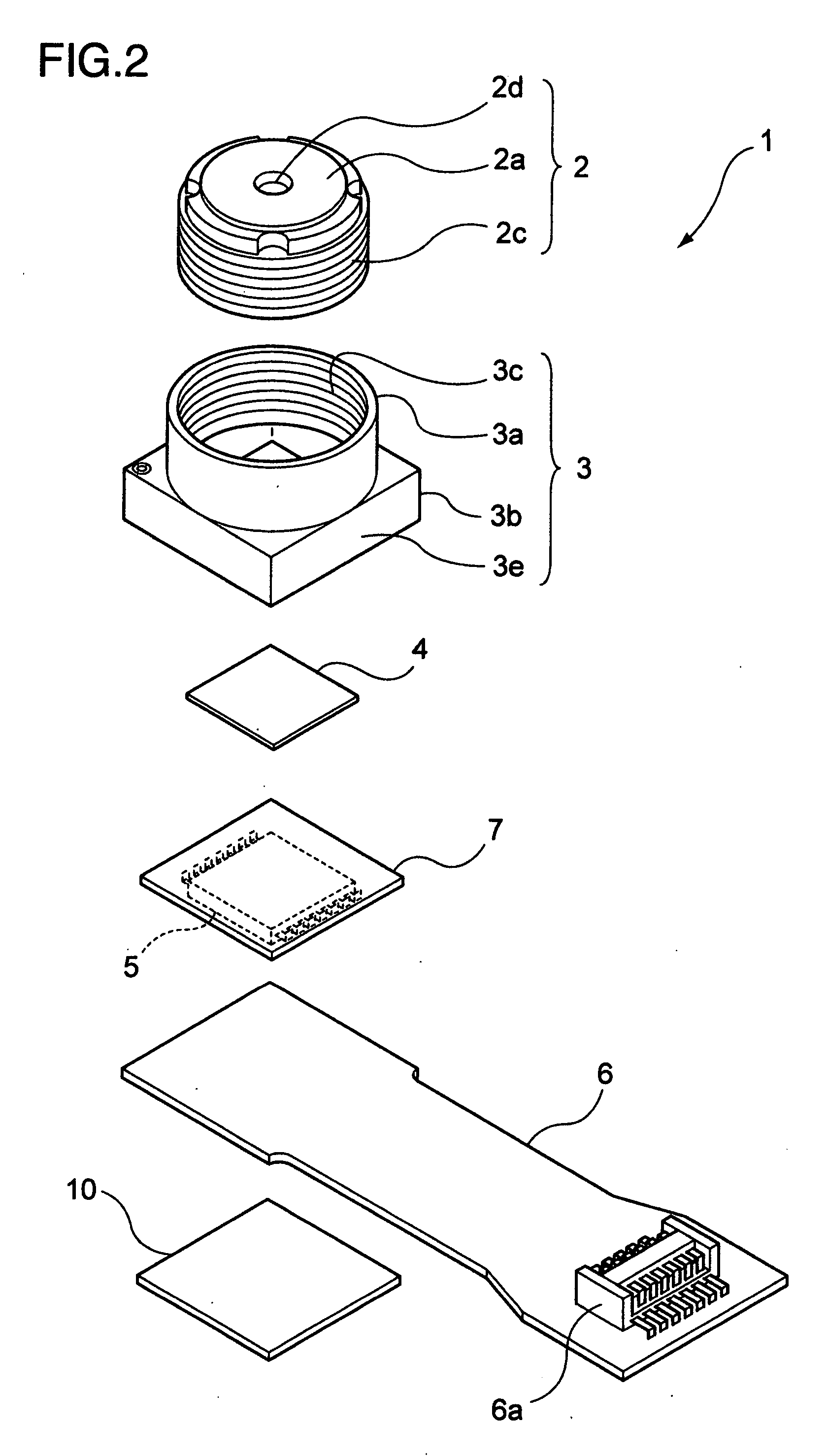
[0032]FIG. 1 shows an appearance of a camera module 1 in an embodiment, and FIG. 2 shows an exploded view of the camera module 1.

[0033]As FIGS. 1 and 2 show, the camera module 1 includes a lens unit 2 which holds a plurality of lenses and which focuses incident light incident thereto onto a sensor 5, a sidewall section 3e to accommodate a filter 4 and the sensor 5, and a pedestal 3 to hold the lens unit 2. In the camera module 1, the filter 4 removes a particular-frequency component from light incident thereto and the sensor 5 converts light incident thereto into an electric signal. The camera module 1 also includes a square glass cover 7 arranged between the filter 4 and the sensor 5 and a Flexible Printed Circuit (FPC) 6 which is fixedly disposed on the pedestal 3 and which transfers an output signal from the sensor 5 to an external device. A re...


PUM


Abstract

A camera module includes a sensor for converting incident light incident thereto into an electric signal and outputting the electric signal therefrom, a glass cover for transmitting therethrough light to the sensor, the light being the incident light; a flexible printed circuit for receiving as an input thereto the electric signal outputted from the sensor, a lens unit for focusing the incident light onto the sensor, and a pedestal for holding the lens unit, the pedestal including a sidewall section which includes a lower end surface being fixed onto the flexible printed circuit by use of adhesive. A depression is formed along the sidewall section of the mount to discard the adhesive therein.

Description

[0001]The present application claims priorities from Japanese applications JP2006-324096 filed on Nov. 30, 2006, JP2006-326059 filed on Dec. 1, 2006, the contents of which are hereby incorporated by reference into this application.BACKGROUND OF THE INVENTION[0002]The present invention relates to a camera module and an imaging apparatus which are to be mounted, for example, on a cellular phone, and in particular, to a camera module and the like suitable to be downsized.[0003]Recently, a camera system is also mounted on a cellular phone and the like. In such camera system, there is broadly used a camera module in which an image of an object is focused onto an image sensor by use of a microlens.[0004]As the cellular phone is reduced in size, it is further required to downsize the camera module.[0005]As a technique associated with a camera module which is downsized and which has high focusing precision, there has been known a conventional technique corresponding to JP-A-2003-51973.[0006...

Claims


Application Information

Patent Timeline
IPC IPC(8): H04N5/225G03B17/48
CPCG03B17/48H04N5/2257H04N5/2251H04N23/57H04N23/55H04N23/00
Inventor AOKI, SUSUMUSHINTA, IKUO
Owner MAXELL HLDG LTD
Why Eureka
Try Eureka