Whirling head and its use

a technology of whirling head and head, which is applied in the direction of turning apparatus, driving apparatus, milling equipment, etc., can solve the problems of not allowing the whirling operation to be performed, production subject to precise constraints,

Inactive Publication Date: 2008-06-05
WILLEMIN MACODEL
View PDF7 Cites 47 Cited by
  • Summary
  • Abstract
  • Description
  • Claims
  • Application Information

AI Technical Summary

Problems solved by technology

The structures of the different types of these screws are currently standardised and their production is subjected to precise constraints.
It has been considered before to make the screw threads by whirling on complex machines of a known type, such as five-axis machining centres with CNC control; however, the relative positions of the spindle and the back working unit, which are fixed in these machines, do not allow the whirling operation to be performed when the set length of the thread requires work with the tailstock centre of the back working unit.

Method used


Image

  • Whirling head and its use
  • Whirling head and its use
  • Whirling head and its use

Examples


Embodiment Construction

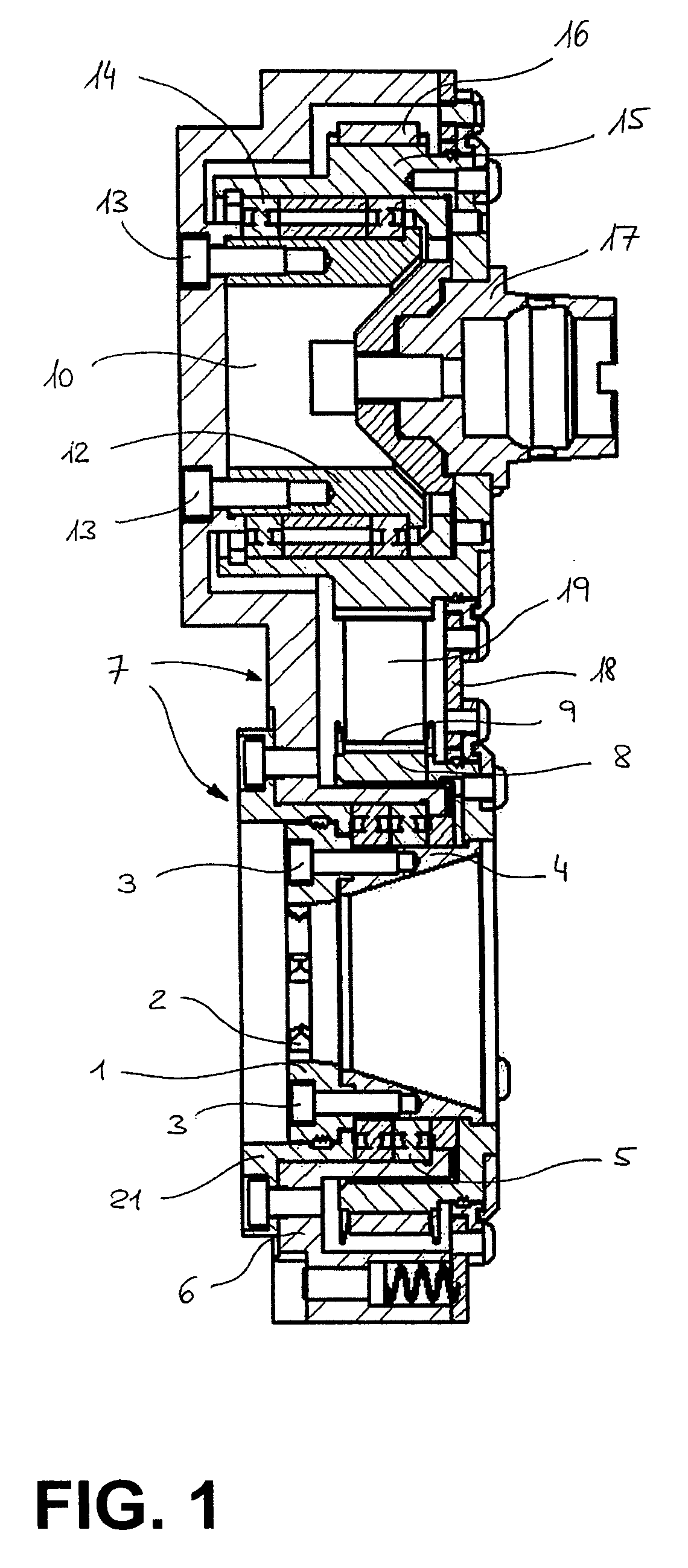
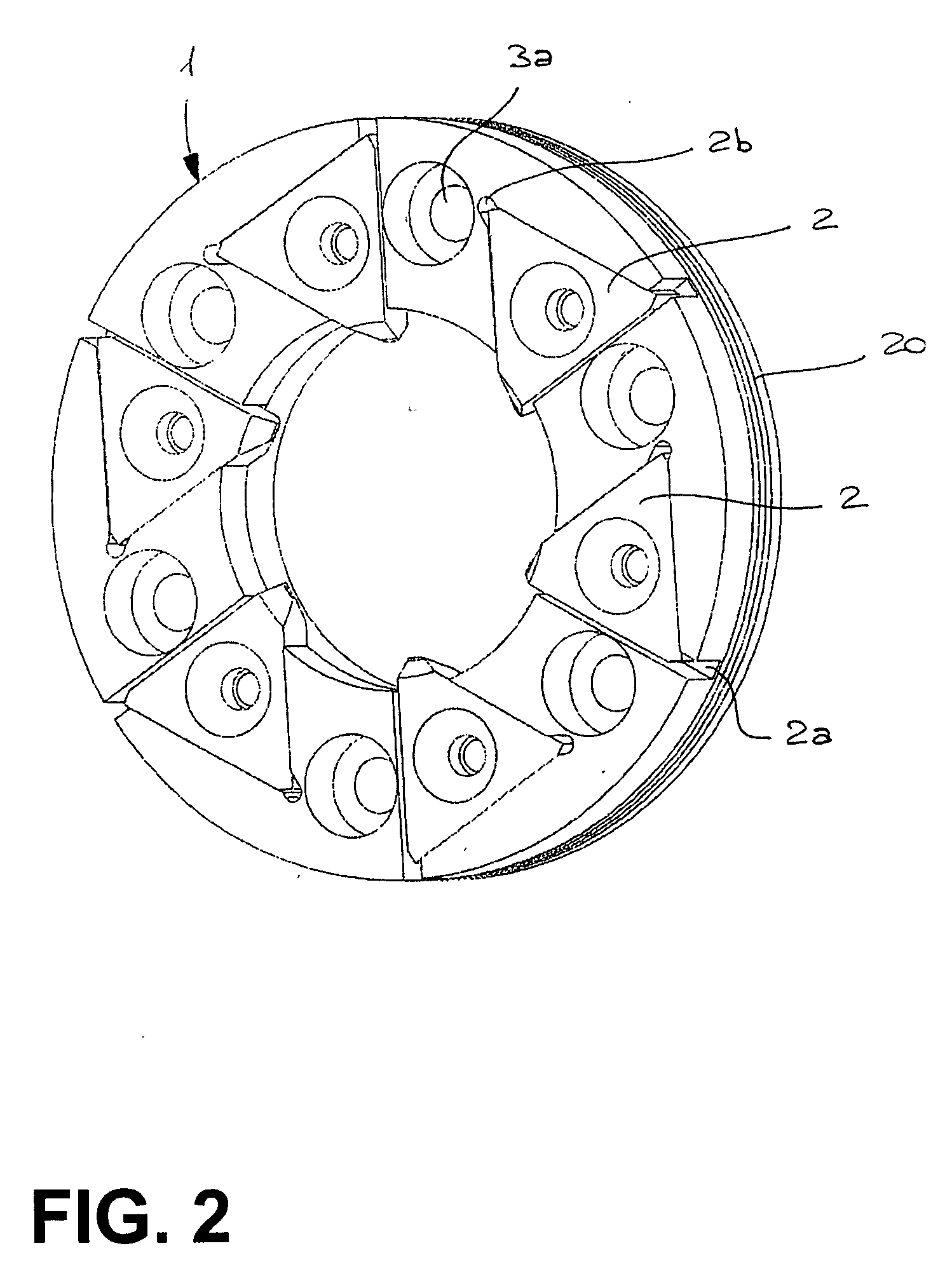
[0017]The section view of FIG. 1 shows the main elements of the whirling head provided as an example. An internal milling cutter 1 equipped with tips 2 is fixed and centred by screws 3 against the rear face of a tubular support with an inner cone 4 which rotates between ball bearings 5, for example made from ceramic. The fixed outer raceways of the bearings 5 are housed in a socket-shaped part 6 of a metal casing 7 forming the main part of the frame of the whirling head. The end of the cone 4 bears a hollow pulley 8 equipped with teeth 9 and comprising a tubular part that covers the socket-shaped part 6 of the casing 7. This is an elongated part with a central portion in the form of a chute having a bottom and a continuous side wall, in which the tubular element 6 projects at one end, surrounded 180 degrees by the wall of the chute. At the other end, the part 7 forms a circular container 10 delimited by the outer side wall of the part. In the bottom of this container is fixed a cyli...


PUM

PropertyMeasurementUnit
helix angleaaaaaaaaaa
lengthsaaaaaaaaaa
structuresaaaaaaaaaa

Abstract

The frame of the whirling head comprises the rigid casing (7), in which the part (10) contains the drive pulley (15) solidly attached to the coupling member (17) connected to the drive shaft of the spindle (26). By means of the belt (19), this pulley (15) drives the pulley (8) solidly attached to the connecting cone (4), which in turn comprises the internal milling cutter (1) which cuts the thread of the screw shaft (27) supported between the bar advance unit (28) and the tailstock centre (29). The latter is mounted as an exchangeable tool on the return unit (32).

Description

TECHNICAL FIELD[0001]The present invention relates to a whirling head with an internal milling cutter, mounted in a frame arranged to be fixed on a body of a spindle in an automatic machining centre, so that the drive shaft of the spindle drives said milling cutter during a whirling operation integrated in a working cycle of said centre. It also relates to the use of such a whirling head on the spindle of a five-axis machining centre.BACKGROUND OF THE INVENTION[0002]The aim of the present invention is to rationalise and improve, in terms of efficiency, the production by machining of certain objects in the medical field, more precisely certain categories of bone screws. Bone screws are commonly used in surgery. The structures of the different types of these screws are currently standardised and their production is subjected to precise constraints. It is known, in particular, that the quality requirements for threading screw shafts require the use of the whirling technique, i.e. cutti...

Claims


Application Information

Patent Timeline
Patent Type & Authority Applications(United States)
IPC IPC(8): B23C3/32
CPCB23C2210/503B23C2220/68B23G1/34Y10T409/30056B23G2240/60B23Q5/046Y10T29/5114B23G5/18
Inventor VOUILLAMOZ, GAEL
Owner WILLEMIN MACODEL
Why Eureka
Try Eureka