
Debris-free plastic collating strip for nails

a collating strip and plastic technology, applied in the field of collating fasteners, can solve the problems of plastic material, nail, shattering and separating from the nail shank, housekeeping problems, etc., and achieve the effect of reducing the impact of the connecting portion and reducing the amount of debris

Active Publication Date: 2008-06-05
ILLINOIS TOOL WORKS INC
View PDF84 Cites 10 Cited by
  • Summary
  • Abstract
  • Description
  • Claims
  • Application Information

AI Technical Summary

Benefits of technology

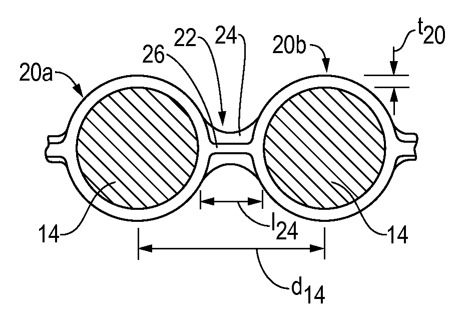
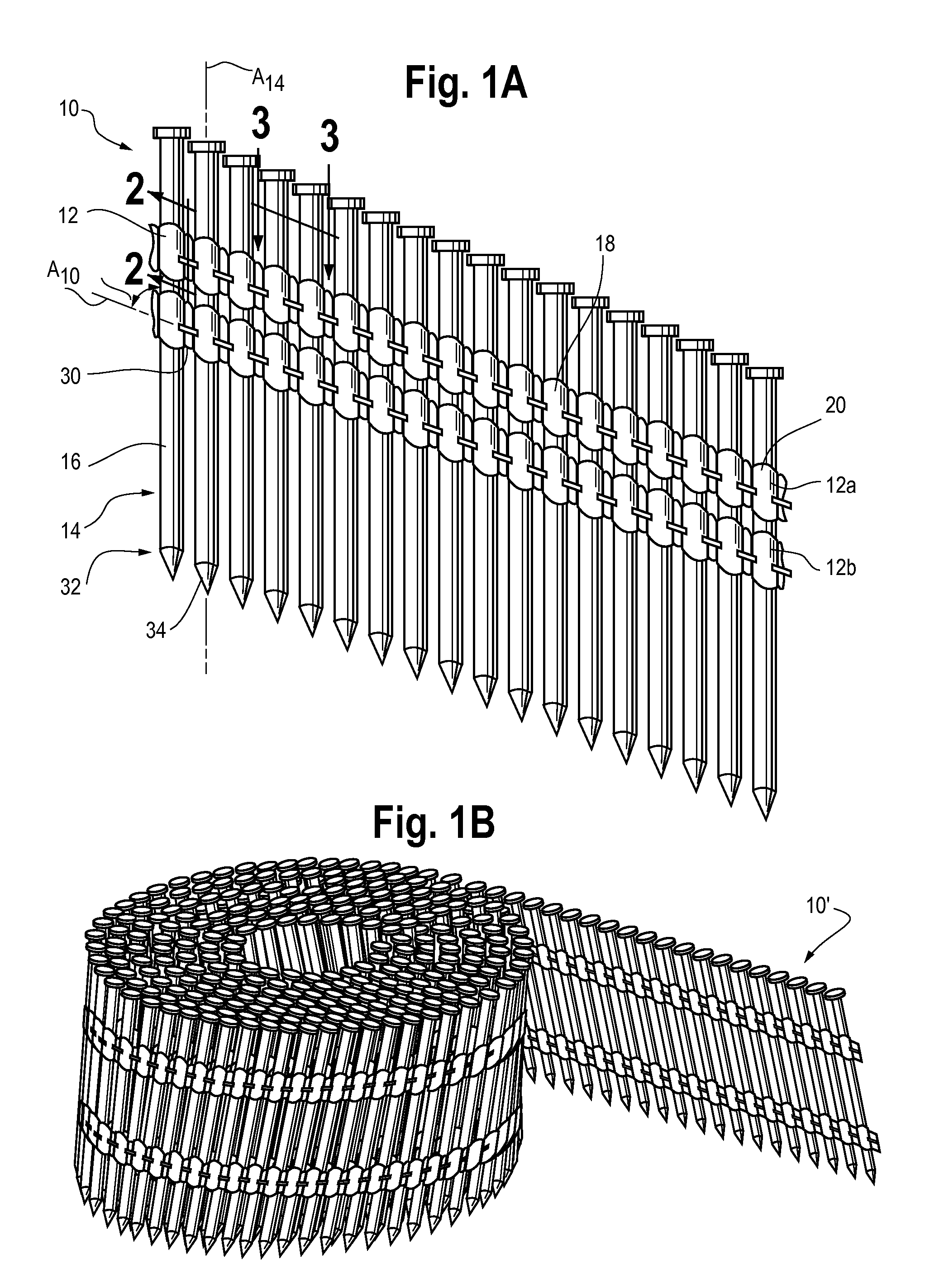
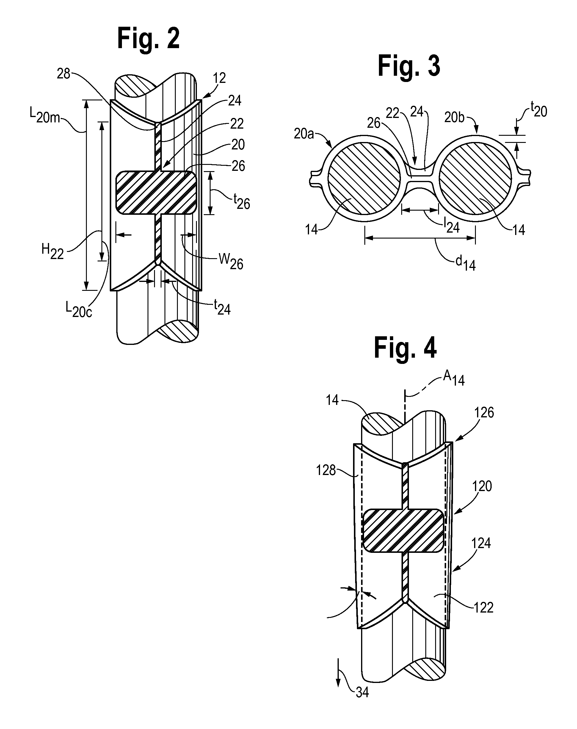
The present invention is a fastener assembly for use in a fastener driving tool. The assembly includes a row of fasteners arranged parallel to each other, with a plastic material molded onto the fasteners to form a collar that captures or encircles the fastener shank. The plastic material is molded onto the fasteners by preheating them and using a molding process. The plastic material can be a blend of polypropylene and maleic anhydride modified polypropylene or an epoxy. The fastener assembly can also include a connecting portion between adjacent fasteners that is weaker than the collar portion, allowing for separation of the connecting portion from the collar at a desired location. The fasteners can also be positioned eccentrically relative to their respective sleeves to create a thin-walled sleeve section at the desired location. The assembly can also include a rib that extends less than the axial length of the collar portion and has a width greater than the collar portion, or a tapered shank. The assembly can also include upper and lower collations that are narrower at the lower end. These features and advantages make the fastener assembly easier to use and more efficient in driving fasteners into a substrate.

Problems solved by technology

However, it has been noted that as the plastic collated nails are driven into the workpiece, the plastic material, not adhering to the nail, shatters and separates from the nail shank.
This can create loose debris at the worksite which can result in housekeeping problems.

Method used


Image

  • Debris-free plastic collating strip for nails
  • Debris-free plastic collating strip for nails
  • Debris-free plastic collating strip for nails

Examples


embodiment 210

[0072]FIGS. 5A and 5B illustrate an embodiment 210 in which the ribs 226 are formed at an angle γ and γ′ relative to an axis A210 of the strip 10 (as opposed to the ribs 26 in the embodiment of FIG. 1 which are generally parallel to the axis A10).

embodiment 310

[0073]FIGS. 6 and 6A illustrate an alternate embodiment of the plastic nail collation 310 in which an embossed pattern 324 is formed in the connecting portion 322 of the strip 310, rather than the bridge 24 and rib 26 configuration (of FIGS. 1-5). In the embossed pattern 324 embodiment, a pattern of ribs 326 is formed in the connecting portion 322 that can extend in one or both directions relative to a plane P322 that is defined by the connecting 322 portion extending between the collars 320 (e.g., into or out of or both into and out of the plane P322 defined by the connecting portion 322 and the adjacent nails 14a,b). A cross-section of a one-directional embossing 324 is illustrated in FIG. 6A. The embossing 324 serves to provide a three-dimensional structure, much like the bridges 24 and ribs 26, to enhance the rigidity of the strip 310. In addition, it is anticipated that the embossing 324 can provide the necessary rigidity and predictability in separation while at the same time,...

embodiment 10

[0076]In order to provide this selectively or preferentially located separation region, a number of configurations have been examined. One such configuration is to include the notch 30 as seen in the embodiment 10 of FIG. 1 and as seen in FIGS. 8A and 8B. To effect separation of the connecting portion 22 as close to the trailing nail 14b as possible, the notch 30 should be positioned as close to the trailing nail 14b as possible.

[0077]Essentially, the strip 10 is configured with a weakened region so that separation is influenced or encouraged at a desired location. However, it should be noted that it is desirable to have the remaining portion of the connecting portion 22 remain intact as the nail 14a is driven into the substrate to reduce the debris generated. Accordingly, as seen in FIG. 8B, the notch 30 can be configured with a semi-circular notch wall 30a, and may also include a lower notch 30b to further influence separation location.

[0078]Another embodiment of the strip 410 can...


PUM


Abstract

A fastener assembly is for use in an associated fastener driving tool. The assembly includes a row of fasteners arranged substantially parallel to each other. Each fastener has a shank and defines an axis. A collation system is formed from a plastic material that is molded onto and adhered to the fasteners. The plastic material defines a collar portion at least substantially encircling the fastener shank and a connecting portion extending between and connecting adjacent collar portions. The connecting portion includes a bridge and a rib. The bridge is a relatively thin, elongate element spanning adjacent collar portions and the rib is a relatively thick, short element that is disposed at about an upper portion of the bridge. When the fastener is driven from the driving tool, the collar portion remains adhered to the fastener such that the collar portion penetrates the substrate with the fastener. The connecting portion can include a weakened region for separating the connecting portion from the collar.

Description

CROSS-REFERENCE TO RELATED APPLICATION DATA[0001]This application is a continuation-in-part of U.S. patent application Ser. No. 11 / 734,684, filed Apr. 12, 2007, which is a continuation-in-part of U.S. patent application Ser. No. 11 / 383,032, filed May 12, 2006.BACKGROUND OF THE INVENTION[0002]The present invention pertains to collated fasteners. More particularly, the present invention pertains to a collated nail strip formed with a debris-free plastic material for use in a fastener driving tool.[0003]Fast-acting fastener driving tools are in widespread use in the construction industry. Such tools are used in industries ranging from re-fabricated housing construction to luxury residential, commercial and industrial construction. For use in these tools, the nails are assembled in strips that are inserted into a magazine of the tool. The strips are flat and the nails or other fasteners are held parallel to one another. The nails are assembled in a staggered or stepped manner such that ...

Claims


Application Information

Patent Timeline
Patent Type & Authority Applications(United States)
IPC IPC(8): F16B15/08
CPCF16B15/08
Inventor HESKEL, ISAAC H.SUOPYS, ALGIS P.STAROZHITSKY, MICHAEL
Owner ILLINOIS TOOL WORKS INC
Learn More