Magnetic retaining device

a magnetic retaining device and magnetic technology, applied in the direction of snap fasteners, buckles, traveling carriers, etc., can solve the problems of not providing much flexibility in where and how the device can be used, and the availability of writing instruments is readily availabl

Inactive Publication Date: 2008-06-12
URYASOV YURIY
View PDF10 Cites 41 Cited by
  • Summary
  • Abstract
  • Description
  • Claims
  • Application Information

AI Technical Summary

Benefits of technology

[0013]Accordingly, it is an object of the present invention to provide a retaining device for a writing instrument which allo

Problems solved by technology

A long standing problem encountered by most people at one time or another is having a writing instrument readily available when needed.
This is frequently a problem when someone is not at a location

Method used


Image

  • Magnetic retaining device
  • Magnetic retaining device

Examples


Embodiment Construction

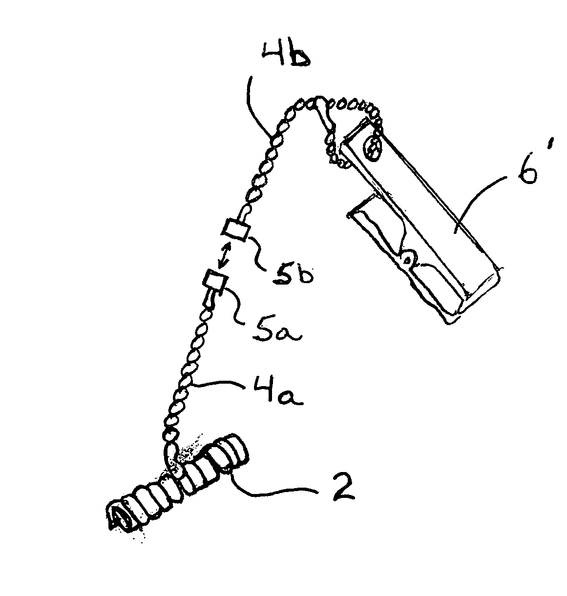
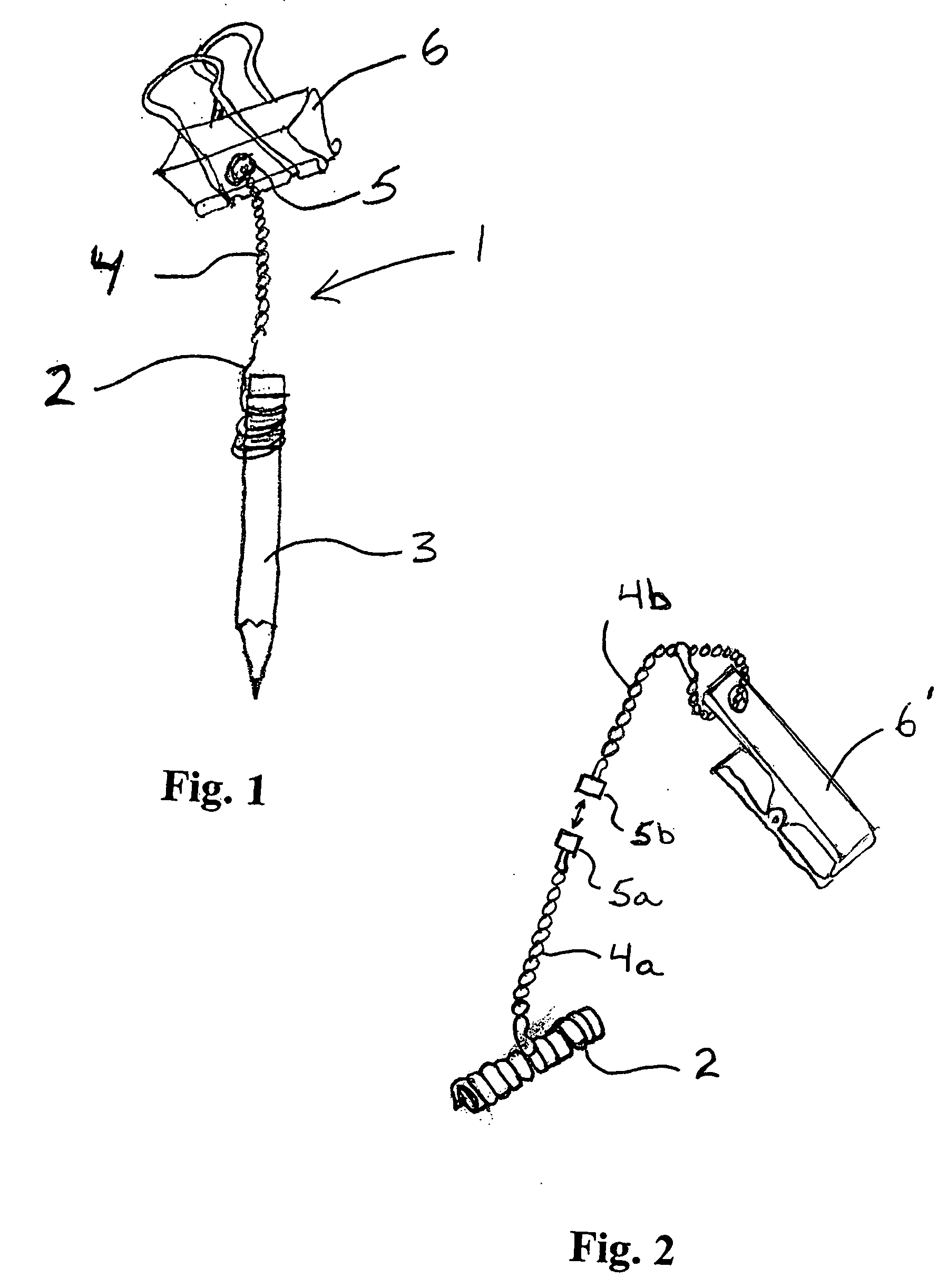
[0022]FIG. 1 shows an embodiment of the retaining device 1 of the present invention. In this embodiment, the retaining device 1 includes a cord 2 with a helically coiled section which has resilient coils that can be enlarged to insert a writing instrument 3. The coils naturally retract to securely hold the writing instrument 3 in place. The free end of the cord 2 is attached to a first end of a ball chain 4. A magnet 5 is attached to the second end of the ball chain 4.

[0023]It is understood that instead of the ball chain 4, any other type of cord can be used which would provide a similar function. For example, a link chain, a nylon string or an elastic member can be used. Additionally, instead of the ball chain 4, it is possible to simply connect the magnet 5 to the free end of the cord 2.

[0024]The cord 2 can be made of any suitable material but preferably is a resilient material such as nylon or plastic. In this way the cord can be coiled near one end for holding the writing instru...


PUM


Abstract

A magnetic retaining device having an elongate member with helical coils at a first end thereof. The helical coils are resiliently expandable so as to hold objects therein. A magnet is attached to a second end of the elongate member to allow the retaining device to be temporarily held on a magnetic surface.

Description

[0001]The present application is a continuation-in-part of co-pending patent application Ser. No. 11 / 637,309, filed Dec. 12, 2006, the entire contents of which are incorporated herein by reference.BACKGROUND OF THE INVENTION[0002]The present invention pertains to a magnetic retaining device, and particularly, to a device for holding a writing instrument for easy access. A long standing problem encountered by most people at one time or another is having a writing instrument readily available when needed. This is frequently a problem when someone is not at a location where a writing instrument is normally readily available, for example, at a desk.[0003]A number of devices have been developed in the past and some of these will be discussed below.[0004]U.S. Pat. No. 6,450,718 discloses a golf bag pencil holder in which a pencil is attached to one end of a flexible cord and the other end of the flexible cord is attached to a snap hook which engages with a ring mounted on a golf bag.[0005...

Claims


Application Information

Patent Timeline
IPC IPC(8): A44B21/00A44B99/00
CPCA45F5/02A45F2200/0566Y10T24/32B43K25/00B43K23/001
Inventor URYASOV, YURIY
Owner URYASOV YURIY
Why Eureka
Try Eureka