Shaving foil for a dry shaver

a shaving foil and dry shaving technology, applied in the field of shaving foil, can solve the problems of dragging the skin of users, not being able to smoothly guide the outer foil, and the accompanying use of thin shaving foil, so as to reduce the thickness and avoid irritation. the effect of skin

Active Publication Date: 2008-06-12
MATSUSHITA ELECTRIC WORKS LTD
View PDF6 Cites 12 Cited by
  • Summary
  • Abstract
  • Description
  • Claims
  • Application Information

AI Technical Summary

Benefits of technology

[0003]In view of the above problem, the present invention has been accomplished to provide a shaving foil for a dry shaver which is capable of assuring close shaving, yet without causing the skin irritation. The shaving foil in accordance with the present invention is configured to a plurality of recesses formed in its top surface defining a skin contact surface to give a thin section of reduced thickness at each of the recesses and to leave thick sections at the remainder of said foil. Each of the perforations is configured to have its circumference defined partly by the thin section and partly by the thick section. With this configuration, both of the thin and thick sections can come into contact with a user's skin for smoothly guiding hairs into the perforations to make close shaving without irritating the skin, while the shaving foil is moved across the skin, during which the thin sections act to cut the hairs shorter than the thick section, and to raise flattened hairs into the perforations for successfully cutting the flattened hairs as well.

Problems solved by technology

However: since the protuberances are distributed separately from each other to give discrete knobs on the shaving foil, they are likely to drag a user's skin and is therefore not suitable for smoothly guiding the outer foil across the skin.
However, the use of the thin shaving foil is certainly accompanied with a drawback of seizing the skin too much into perforations of the foil and irritating the skin.

Method used


Image

  • Shaving foil for a dry shaver
  • Shaving foil for a dry shaver
  • Shaving foil for a dry shaver

Examples


Embodiment Construction

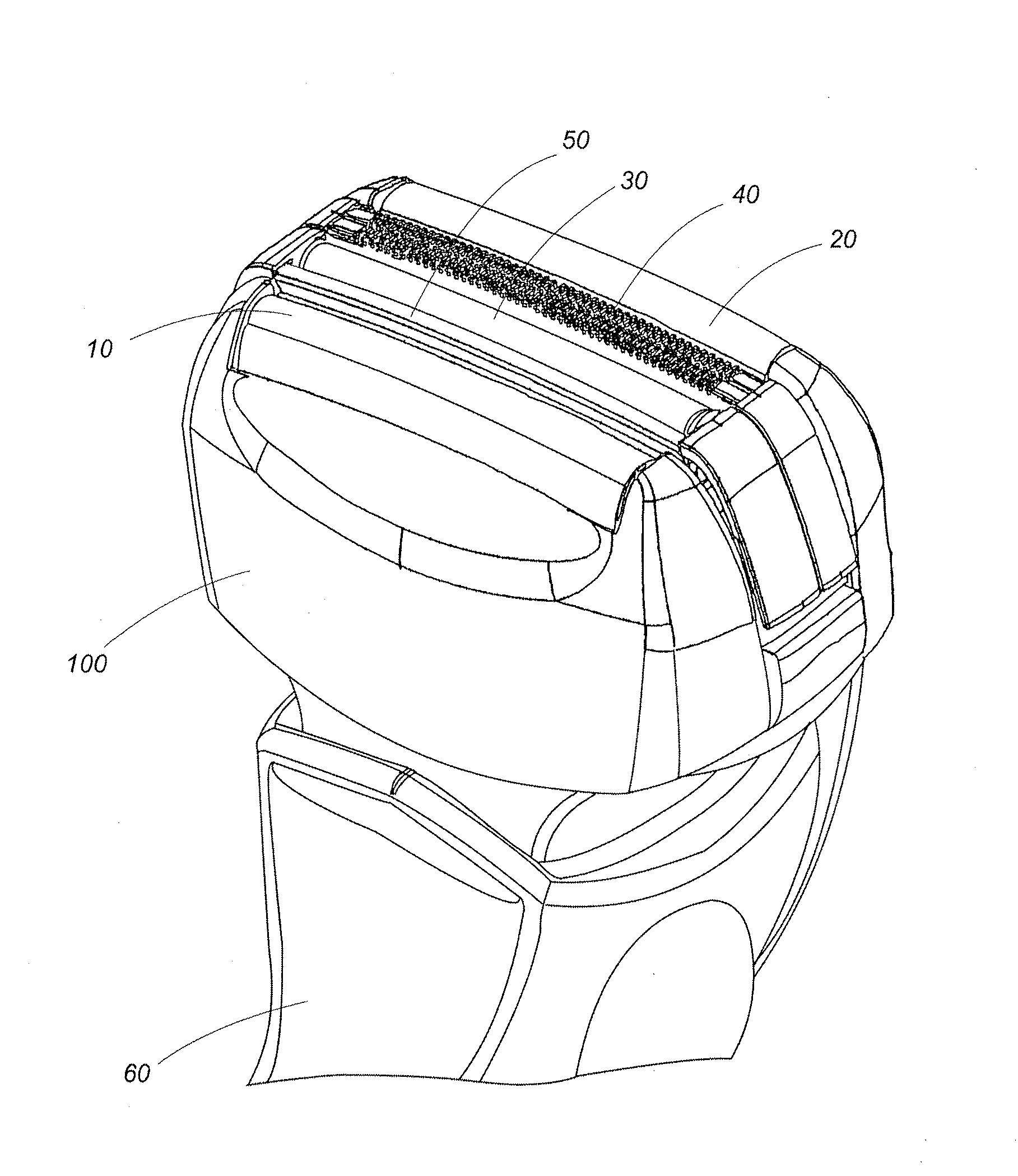
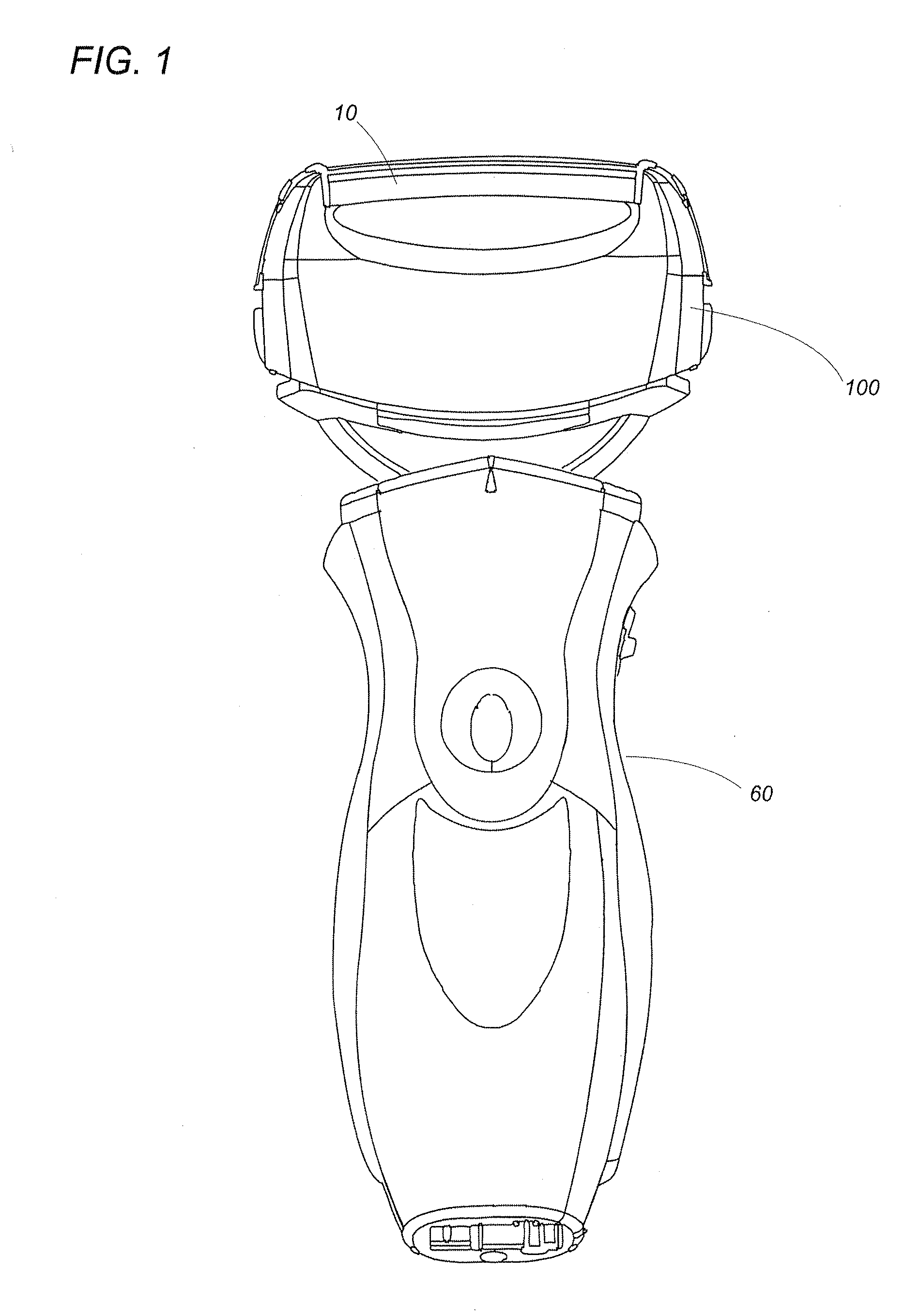
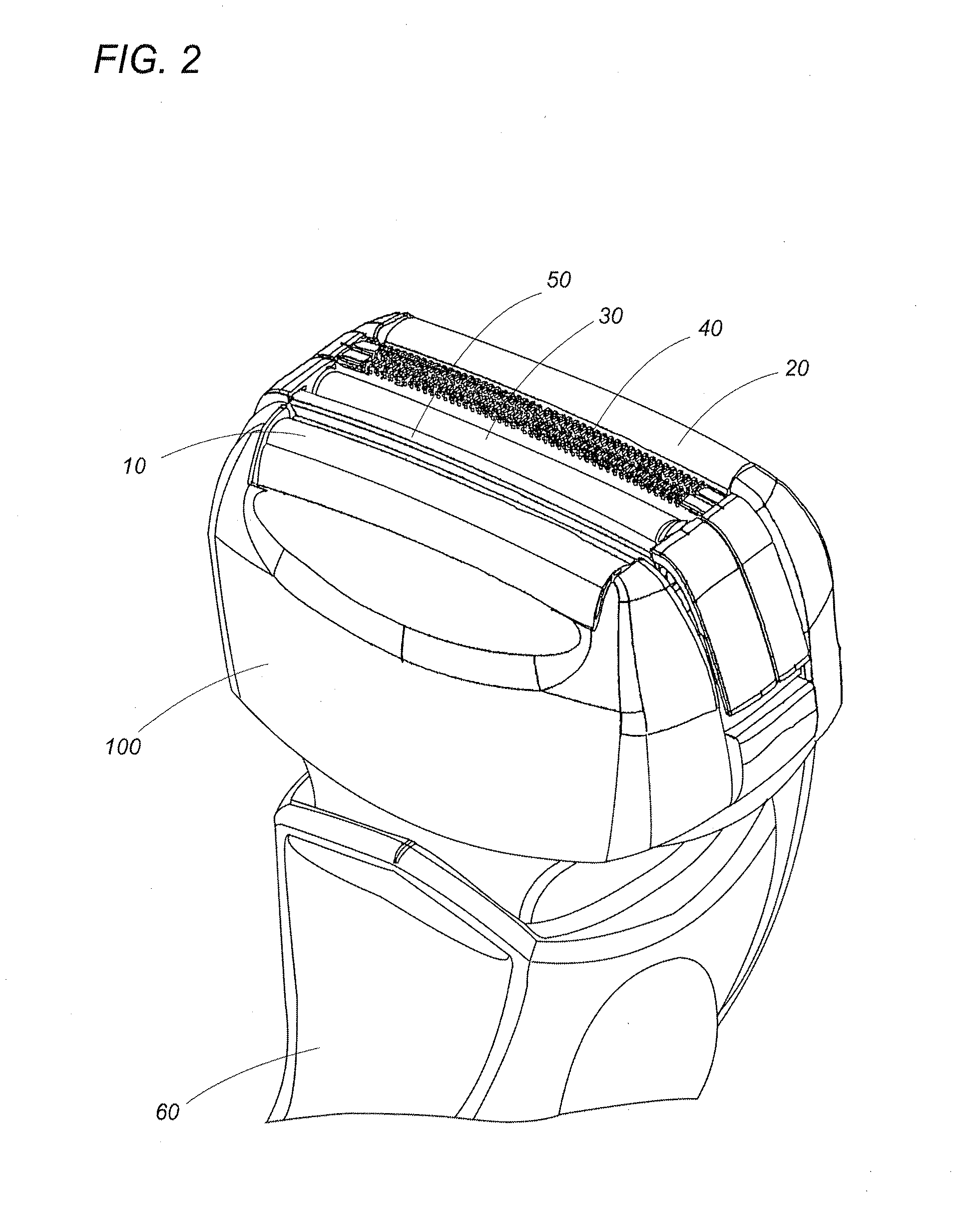
[0026]Referring now to FIGS. 1 to 5, there is shown a dry shaver utilizing a shaving foil in accordance with a preferred embodiment of the present invention. The dry shaver is composed of a hand grip 60 and a shaving head 100 mounted on top of the hand grip60. The shaving head 100, which is elongated to have a lengthwise axis and a width axis, is connected to the grip 60 to be movable relative thereto about an axis perpendicular to the lengthwise axis. The shaving head 100 carries four differently configured cutters, namely, a semi-cylindrical first outer cutter 10, a semi-cylindrical second outer cutter 20, a semi-cylindrical finishing cutter 30, and a slit cutter 40. These cutters are all elongated along the lengthwise axis of the shaving head 100 and arranged in parallel relation with each other along the width axis.

[0027]The shaving head 100 is composed of a casing 120 and a frame 130 detachable to the casing 120. The casing 120 is of a water-proof structure accommodating therei...


PUM


Abstract

A shaving foil for a dry shaver has a plurality of perforation arranged in an array. The shaving foil is formed in its skin contact surface with a plurality of recesses which define a thin section of reduced thickness at the recesses, while leaving thick sections at the remainder of the foil. Each perforation is configured to have its circumference defined partly by the thin section and partly by the thick section. Both of the thin and thick sections can come into contact with a user's skin for smoothly guiding hairs into the perforations to make close shaving without irritating the skin, while the shaving foil is moved across the skin. Especially, the thin sections act to cut the hairs shorter than the thick section, as wall as to raise flattened hairs into the perforations for successfully cutting the flattened hairs.

Description

TECHNICAL FIELD[0001]The present invention is directed to a shaving foil for use in a dry shaver.BACKGROUND ART[0002]U.S. Pat. No. 5,185,933 discloses a shaving foil for a dry shaver which is configured to have protuberances on a skin engaging surface of the foil in order to raise flattened hairs for efficient shaving. However: since the protuberances are distributed separately from each other to give discrete knobs on the shaving foil, they are likely to drag a user's skin and is therefore not suitable for smoothly guiding the outer foil across the skin. It is generally known that the shaving foil of reduced-thickness is effective to make a close shaving of cutting relatively straight hairs, as well as to raise flattened hairs for effectively cutting such hairs. However, the use of the thin shaving foil is certainly accompanied with a drawback of seizing the skin too much into perforations of the foil and irritating the skin. Accordingly, it has been a demand of making the close sh...

Claims


Application Information

Patent Timeline
Patent Type & Authority Applications(United States)
IPC IPC(8): B26B19/38
CPCB26B19/384B26B19/38B26B19/42
Inventor KOMORI, SHUNSUKEIWASAKI, JYUZAEMONSHIMIZU, HIROAKISHIBA, TAKESHISATO, MASAAKI
Owner MATSUSHITA ELECTRIC WORKS LTD
Why Eureka
Try Eureka