Auto-sampler cleaning mechanism

a cleaning mechanism and auto-sampler technology, applied in the field of sample introduction devices, can solve the problems of difficult to accurately stop the flow of liquid, the volume may increase occasionally, and achieve the effect of high resistan

Inactive Publication Date: 2008-06-12
SHIMADZU CORP
View PDF10 Cites 26 Cited by
  • Summary
  • Abstract
  • Description
  • Claims
  • Application Information

AI Technical Summary

Benefits of technology

[0017]According to the present invention, as a diaphragm pump is used when supplying the cleaning solution, the cleaning mechanism of the present invention is capable of maintaining the supply of the cleaning solution in a non-time-consuming manner, which is unlike the conventional pump or syringe mechanism.
[0018]Furthermore, when the liquid-supply valve at the upstream of the diaphragm pump has a plurality of ports for supplying more than two cleaning solutions, a plurality of cleaning solutions may be selected and supplied.
[0019]The diaphragm pump is generally used under a fixed voltage, but the flow of the supplied liquid cannot be controlled at this situation. Additionally, when the flow path has a relatively high resistance, the diaphragm pump may not supply the liquid. A...

Problems solved by technology

Furthermore, if a larger amount of samples is introduced, the dead volume may increase occasionally.
In this manner, as the cleaning solution cannot be supplied during the suction process, even if the amount of the supplied liquid is expected to i...

Method used


Image

  • Auto-sampler cleaning mechanism
  • Auto-sampler cleaning mechanism
  • Auto-sampler cleaning mechanism

Examples


Embodiment Construction

[0026]Embodiments of the present invention are illustrated below.

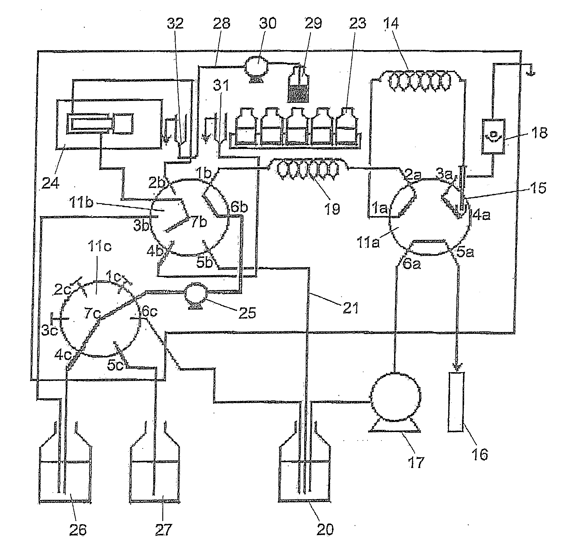
[0027]FIG. 1 is a general structural view of an auto-sampler cleaning mechanism.

[0028]A sample loop 14 is connected to a port 1a of a multi-ported valve 11a hand has a sample-injecting needle 15 at a front end thereof. A port 5a of the valve 11a is connected to a column 16, and a port 6a of the valve 11a is connected to a pump 17.

[0029]A flow path 19 is disposed between a port 1b of a multi-position valve 11b and a port 2a of the valve 11a, such that a liquid with the same volume as the sample in the sample loop 14 may be stored. A port 5b of the valve 11b is connected to a mobile-phase-supply flow path 21 for the liquid supply pump 17 to supply a mobile phase 20. Furthermore, a port 2b of the valve 11b and a common port 7b of the valve 11b are connected to a metering pump 24 for metering the volume of the liquid.

[0030]A cleaning solution port 6b of the valve 11b is connected to a common port 7c of a liquid-supply valv...


PUM


Abstract

An auto-sampler cleaning mechanism is provided, which is capable of maintaining the supply of a liquid in a non-time-consuming manner when a cleaning solution is supplied. The auto-sampler cleaning mechanism of the present invention includes: a sample-metering sample loop 14 having a sample-injecting needle 15 at a front end thereof, a metering pump 24, a multi-ported valve 11a, a multi-position valve 11b, and a liquid-supply valve 11c. A diaphragm pump 25 is disposed between the port of the multi-position valve 11a and the port of the liquid-supply valve 11b, and used to supply a cleaning solution 26 or a mobile phase 20 to the sample loop 14.

Description

CROSS-REFERENCE TO RELATED APPLICATION[0001]This application claims the priority benefit of Japan application serial no. 2006-328979, filed on Dec. 6, 2006. The entirety of the above-mentioned patent application is hereby incorporated by reference herein and made a part of this specification.BACKGROUND OF THE INVENTION[0002]1. Field of the Invention[0003]The present invention relates a sample introduction device for introducing a sample into an analysis apparatus, such as liquid chromatograph. More particularly, the present invention relates to a total injection auto-sampler cleaning mechanism.[0004]2. Description of Related Art[0005]Total injection refers to a total amount of samples, taken from a sample bottle and metered by a sample needle, is completely injected from an injection port.[0006]As for a sample introduction device capable of performing high precision metering regardless of the samples are micro samples or macro samples, it includes a metering pump and a multi-positio...

Claims


Application Information

Patent Timeline
IPC IPC(8): G01N1/28
CPCG01N35/1097G01N35/1004
Inventor MAEDA, YOSHIAKITATSUMI, NOBUYUKI
Owner SHIMADZU CORP
Why Eureka
Try Eureka