Right double lumen endobronchial tube

a technology of endobronchial tube and right lumen, which is applied in the field of right double lumen tube, can solve the problems of anomalous ventilation of the lung, difficulty in properly aligning the lateral orifice of the r-dlt and maintaining alignment, and difficulty in repositioning, so as to promote routine use and facilitate positioning

Inactive Publication Date: 2008-06-12
UNIV LAVAL
View PDF20 Cites 13 Cited by
  • Summary
  • Abstract
  • Description
  • Claims
  • Application Information

AI Technical Summary

Benefits of technology

[0016]It is therefore an object of this invention to provide an R-DLT that is easy to position in a safe and effective manner so as to promote routine use thereof by all anesthesiologists

Problems solved by technology

Despite accurate initial placement of an endobronchial tube, movement can occur during anesthesia and surgery, and repositioning can be difficult.
The difficulty lies in properly aligning the lateral orifice of the R-DLT and in maintaining the alignment thereof throughout the entire surgery.
In a case where optimal lateral orifice placement of the R-DLT is not realized, there lays a risk of anomalous ventilation of the lung which could result in clinical repercussions such as right upper lobe atelectasis and secondary hypoxemia.
The author arrives at the conclusion that “right-sided DLTs should not be used routinely in thoracic surgery.” The R-DLT is criticized for being more difficult to position and to manage during postoperative ventilation, also for having a high incidence of right upper lobe obstruction, and for being twice as expensive as left-sided DLTs (page 251, para.
Also, the authors have the opinion that “right-sided tubes are designed as well as they can be, and the margin of safety in positioning right-sided tubes cannot be improved” (page 738, para.
Thus, anesthesiologists have generally become less skilled at operating with a R-DLT because of a lack of practice.
However, when an absolute need to use a R-DLT arises, which is approximately 1-2% of surgical cases, anesthesiologists end up performing a surgery that they are not comfortable with.
Consequently, the likelihood of complications occurring increases which is detrimental to the patient.
Therefore, avoiding a particular practice in fact negatively impacts the anesthesiologists and in turns their patients.
Although suggestions have been made concerning modifications to the R-DLT, none have proven to be fruitful in maintaining the lateral orifice optimally positioned with respect to the right upper lobe bronchus.
Greatly, this is because up until now, the underlying problem behind the failing attempts at positioning the R-DLT has not been identified.

Method used


Image

  • Right double lumen endobronchial tube
  • Right double lumen endobronchial tube
  • Right double lumen endobronchial tube

Examples


Embodiment Construction

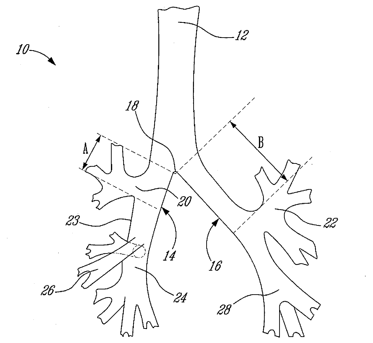
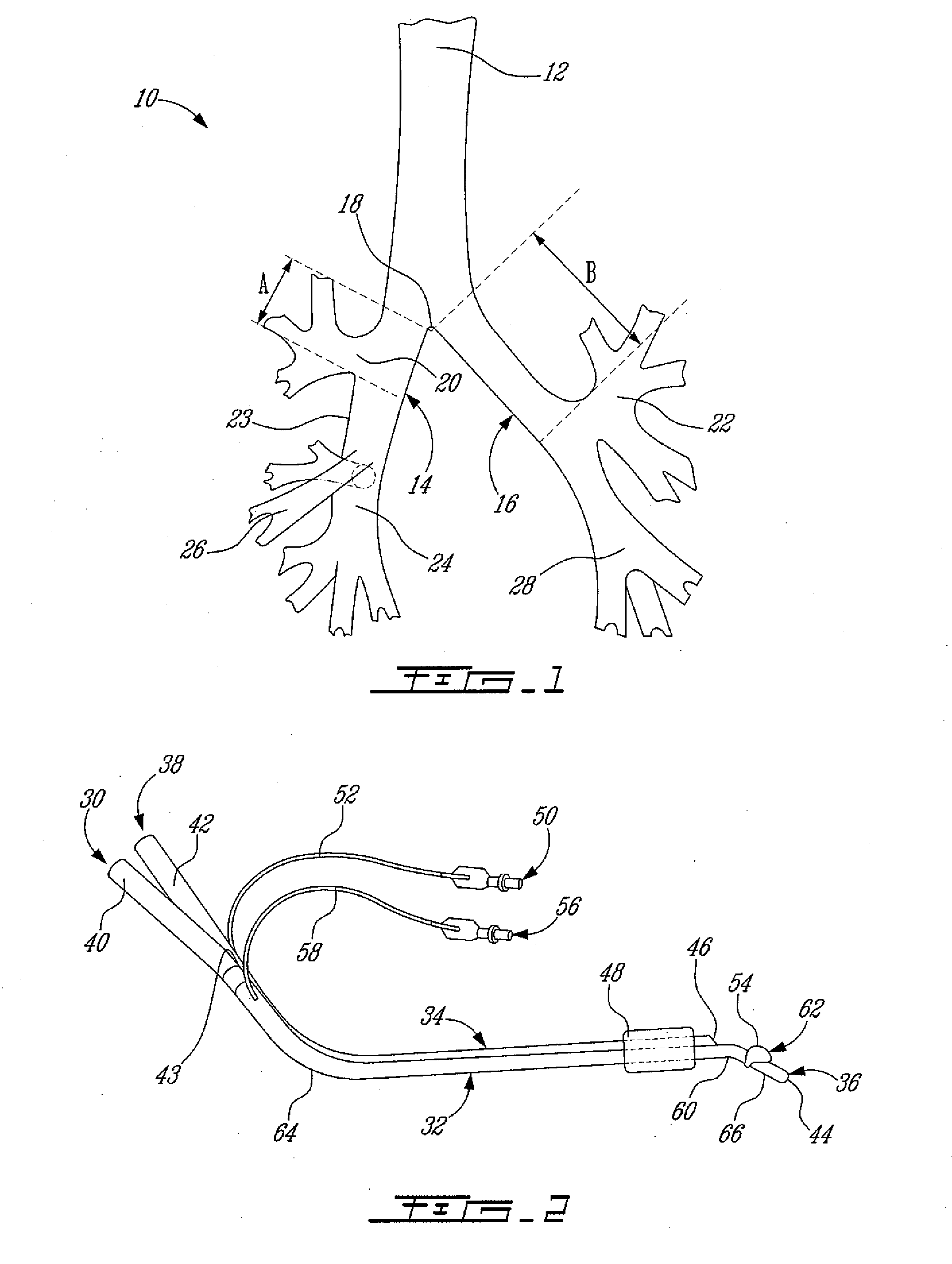
[0035]FIG. 1 illustrates the anatomy of the tracheobronchial tree represented by reference numeral 10. It can be seen that the tracheobronchial tree 10 comprises a trachea 12 that bifurcates into a right main bronchus 14 and a left main bronchus 16. The right main bronchus 14 branches off the trachea 12 at an approximate angle of 25 degrees and the left main bronchus 16 branches off at an approximate angle of 45 degrees. These are the major air passages from the trachea 12 to the lungs (not shown). Each lung is divided into upper and lower lobes, with the right lung also having a triangular division known as the middle lobe. The right lung is larger and heavier than the left lung, which is somewhat smaller in size because of the position of the heart. The main bronchi 14 and 16 enter each lung respectively and progressively branch off into more than 23 paired subdivisions. At every branching, the number of airways increases greatly. Thus, FIG. 1 illustrates a portion of the entire s...


PUM


Abstract

A right-sided double lumen tube (R-DLT) that is easy to position in a safe and effective manner so as to promote routine use thereof by all anesthesiologists. The R-DLT designed to facilitate the alignment of the lateral orifice thereof with the right upper lobe bronchus. The lateral orifice having an angular width of at least 80 degrees of 360 degrees of the circumference of a tube of the R-DLT.

Description

RELATED APPLICATION(S)[0001]This application is a continuation of International Patent Application No. PCT / CA2006 / 000959 filed on Jun. 9, 2006, which claims benefit of U.S. Patent Application No. 60 / 689,098 filed on Jun. 10, 2005, which are herein incorporated by reference.TECHNICAL FIELD[0002]The invention relates generally to a right double lumen tube used in endobronchial intubation for thoracic surgery, and more particularly to an improved right double lumen tube facilitating the alignment of the lateral orifice thereof with the right upper lobe bronchus.BACKGROUND OF THE INVENTION[0003]Anesthetic techniques for thoracic surgery, either pulmonary or oesophageal necessitate the execution of endobronchial intubation. A variety of artificial airway devices have been developed to permit isolation of the lungs and to facilitate one lung ventilation (OLV). Separation of the lungs prevents the spread of secretions, pus and blood from one lung to the other. OLV is a process in which one...

Claims


Application Information

Patent Timeline
Patent Type & Authority Applications(United States)
IPC IPC(8): A61M16/00
CPCA61B2017/00809A61B2017/22069A61M16/04A61M16/0486A61M16/0418A61M16/042A61M16/0459A61M16/0434A61M16/0404
Inventor BUSSIERES, JEAN
Owner UNIV LAVAL
Why Eureka
Try Eureka