Zero turning radius vehicle control mechanism

a vehicle control and zero-turning technology, applied in the direction of mechanical control devices manual control with multiple control members, etc., can solve the problem of not being immediately intuitive for a new driver

Inactive Publication Date: 2008-06-12
TORQUE HLDG
View PDF2 Cites 19 Cited by
  • Summary
  • Abstract
  • Description
  • Claims
  • Application Information

AI Technical Summary

Benefits of technology

[0073]wherein the movement of said steering wheel is, via said coupling members, capable of displacing both said first push-pull rod and said second push-pull rod along said lever arm to displace first push-pull rod and/or said seco

Problems solved by technology

A disadvantage of this system is that it is not immediately

Method used


Image

  • Zero turning radius vehicle control mechanism
  • Zero turning radius vehicle control mechanism
  • Zero turning radius vehicle control mechanism

Examples


Embodiment Construction

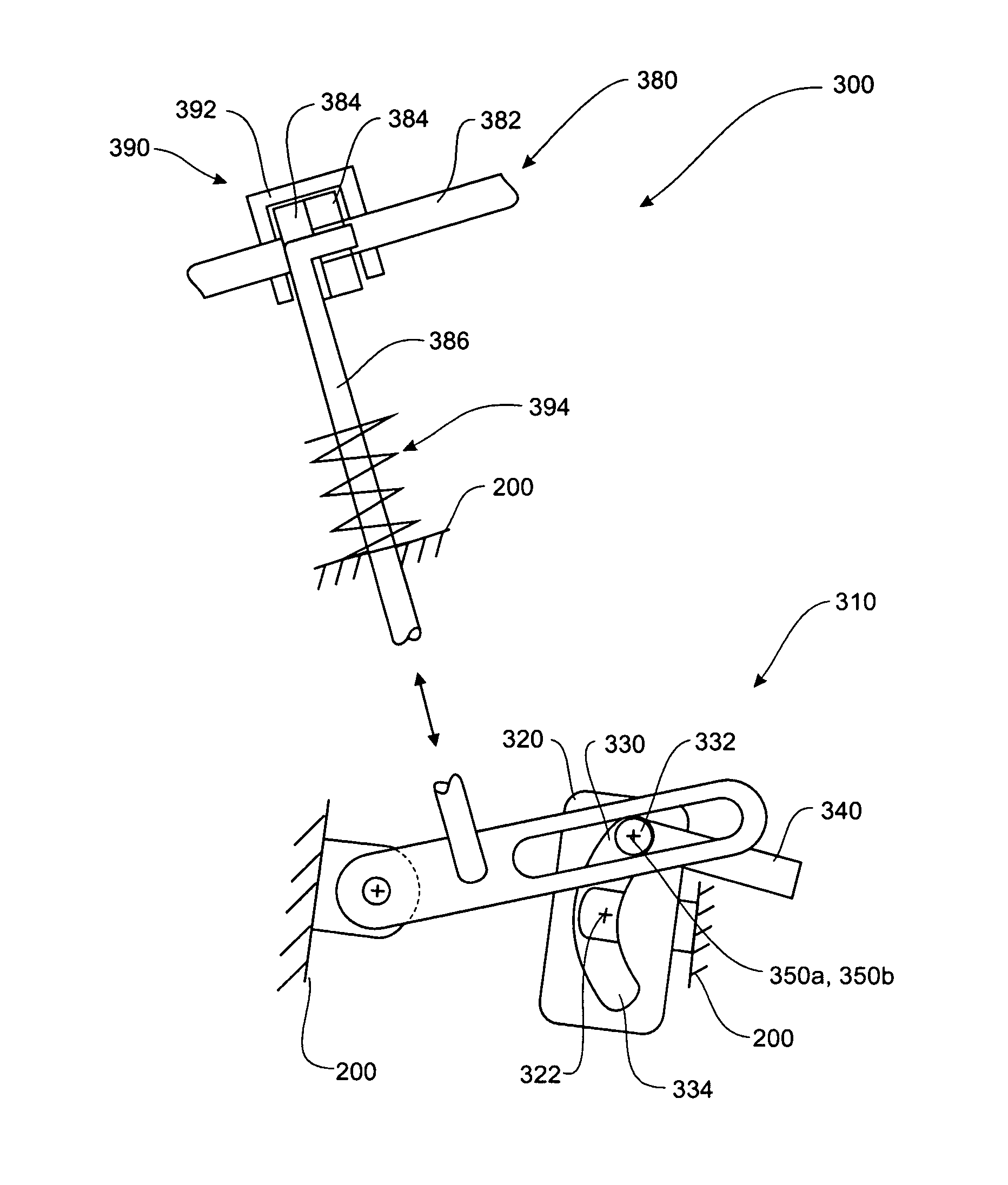
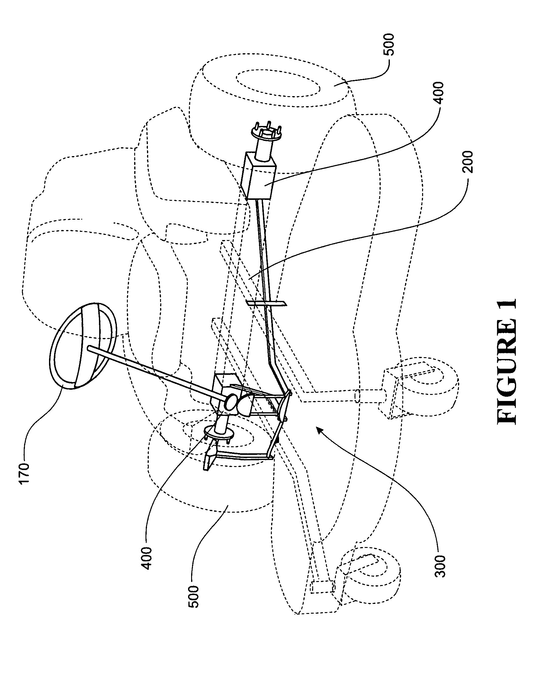
[0104]With reference to FIG. 1 there is shown a vehicle (e.g. a lawn mower) that includes a steering and drive control arrangement generally indicated by the numeral 300.

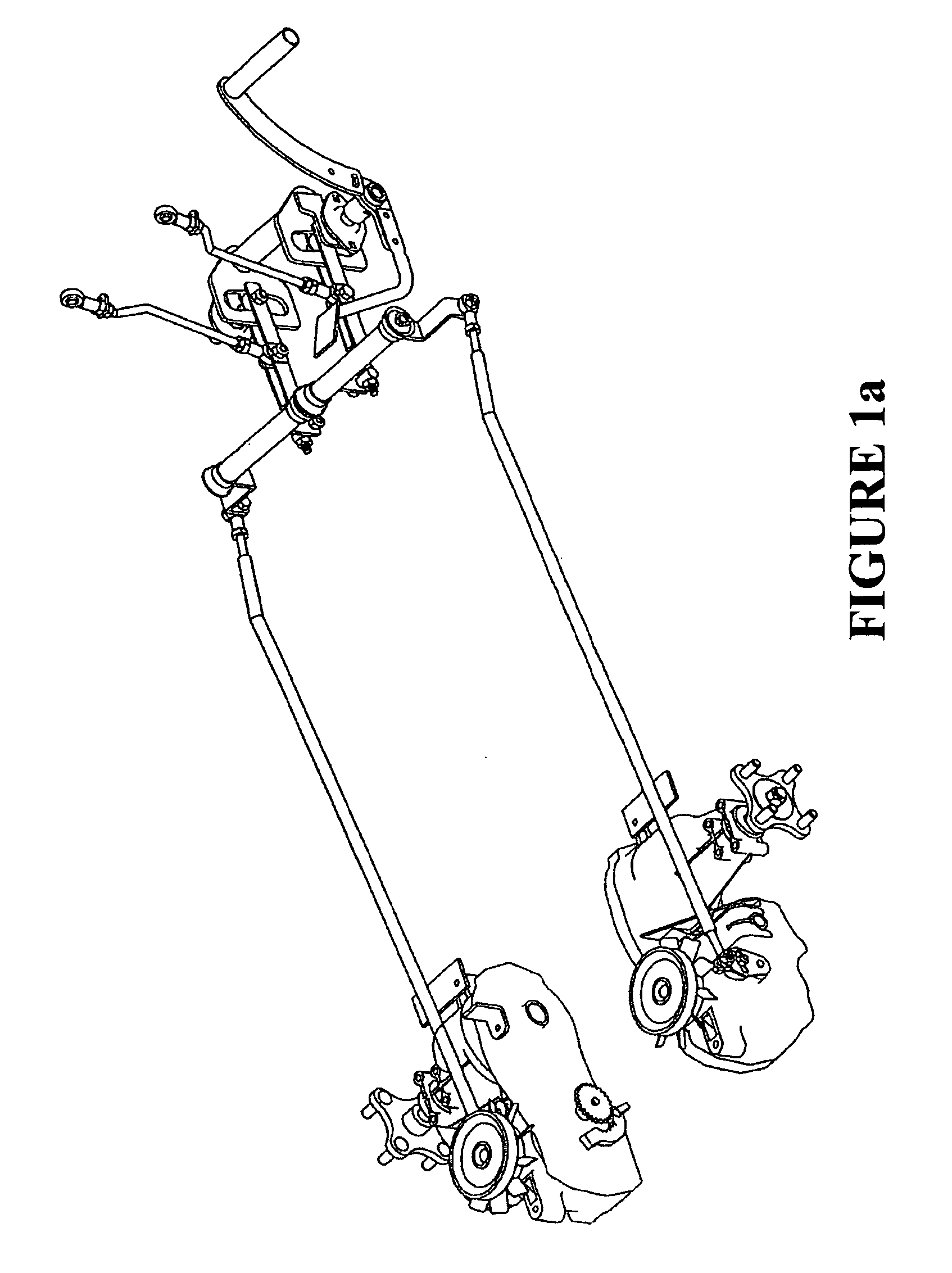
[0105]The steering and drive control arrangement 300 may be suitable for a vehicle having independent transmission systems to drive two traction elements such as in the form of driving wheels and a vehicle chassis 200.

[0106]A steering wheel 170 is pivotally connected to the vehicle chassis 200.

[0107]With reference to the FIGS. 1-8, a steering and drive control arrangement is generally indicated by the numeral 300.

[0108]The steering and drive control arrangement 300 is suitable for a vehicle having a vehicle chassis 200 and a pair of transmission systems for independently driving two traction elements such as drive wheels as herein before described.

[0109]The control arrangement 300 comprises a drive assembly 310 including a pivot member 320, which is pivotally movable relative to the chassis around a pivot axis 322. ...


PUM


Abstract

A zero turning radius vehicle is disclosed that has a steering and drive control mechanism that includes a steering wheel and an accelerator pedal. The mechanism includes push-pull rods to effect movement of throttle levers on motors that independently drive traction elements such as wheels or traction belts. The position of each push-pull rod can be controlled by both the steering wheel and the accelerator pedal such that both the wheel and accelerator pedal can control the throttle of each motor independently or proportionally to thereby effect a change in vehicle speed and/or direction of travel.

Description

FIELD OF THE INVENTION[0001]The present invention relates to zero turning radius vehicle control mechanism, and in particular a steering and drive control arrangement for a zero-radius turning vehicle.BACKGROUND OF THE INVENTION[0002]The use of zero radius turn vehicles is well known in several industries. In particular, they are well known for use in tracked armoured vehicles, and for ride-on lawn mowers. The use of zero radius turn vehicles is particularly advantageous where the vehicles are required to move in tight or confined spaces, or where they are required to follow staggered lines of movement.[0003]The steering control systems used with these vehicles usually involve a pair of levers that each control the forward or backward movement of a wheel or drive system to a wheel. By pushing or pulling on each lever, the corresponding wheel of drive system (such as a track) is caused to move forwards or backwards respectively, and by pushing on one lever while pulling on another, t...

Claims


Application Information

Patent Timeline
IPC IPC(8): G05G13/00B62D7/00B62D1/02
CPCB62D11/006Y10T74/20256B62D11/04
Inventor MCCOID, TREVOR ALBERTWHITE, DAVID EDWARD
Owner TORQUE HLDG
Why Eureka
Try Eureka