Load control system having a plurality of repeater devices

a repeater device and control system technology, applied in the field of load control system, can solve the problems that the control device cannot be wired using a web, star, or “free-wiring” topology

Inactive Publication Date: 2008-06-12
LUTRON TECH CO LLC
View PDF14 Cites 66 Cited by
  • Summary
  • Abstract
  • Description
  • Claims
  • Application Information

AI Technical Summary

Benefits of technology

[0014]According to the present invention, a load control system for controlling the amount of power delivered to a plurality of electrical loads from an AC power source comprises a plurality of link power supply devices, a plurality of device communication links, a plurality of control devices, and a repeater communication link. Each link power supply device includes first and second communication ports, and an internal power supply for receiving a supply voltage and for generating a link voltage. Each of the device communication links is coupled to the first communication port of one of the plurality of link power supply devices. Each of the control devices is coupled to one of the plurality of device communication links. The link voltages of the link power supplies are provided on the device communication links, such that the control devices are operable to draw current from the link power supply devices. The control devices are operable to transmit and receive first digital messages between each other via the device communication links. The repeater communication link is coupled to the second communication port of each of the link power supply devices. The link power supply devices are each operable to receive the first digital messages via the first communication port and to subsequently transmit second digital messages on the repeater communication link via the second communication port. The second digital messages are substantially the same as the first digital messages. No control devices are coupled to the repeater communication link, such that no control devices draw current through the repeater communication link.

Problems solved by technology

The control devices cannot be wired using a web, star, or “free-wiring” topology.

Method used


Image

  • Load control system having a plurality of repeater devices
  • Load control system having a plurality of repeater devices
  • Load control system having a plurality of repeater devices

Examples


Embodiment Construction

[0023]The foregoing summary, as well as the following detailed description of the preferred embodiments, is better understood when read in conjunction with the appended drawings. For the purposes of illustrating the invention, there is shown in the drawings an embodiment that is presently preferred, in which like numerals represent similar parts throughout the several views of the drawings, it being understood, however, that the invention is not limited to the specific methods and instrumentalities disclosed.

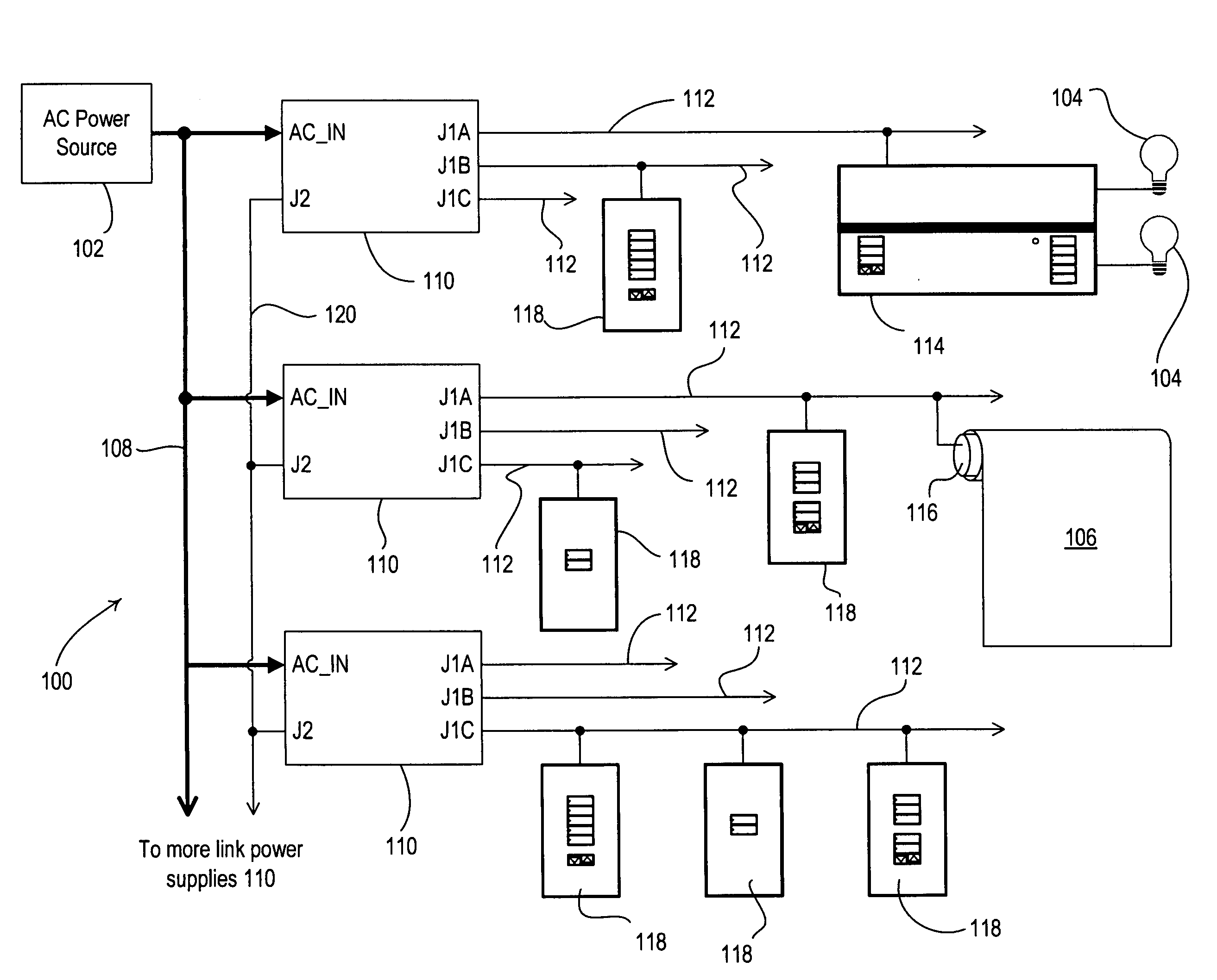
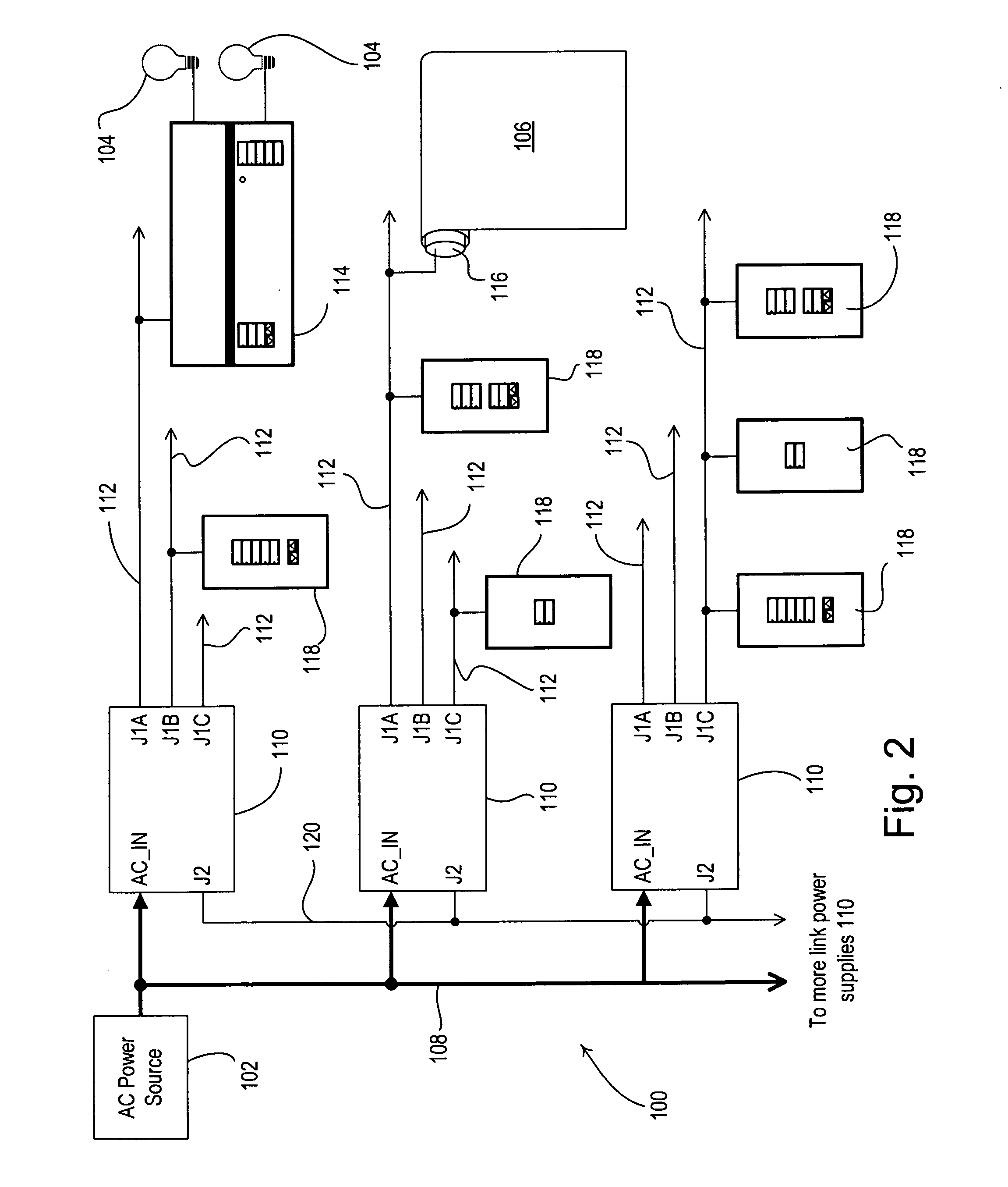
[0024]FIG. 2 is a simplified block diagram of a load control system 100 for control of a plurality of lighting loads 104 and a plurality of motorized window treatments, e.g., motorized roller shades 106, from an AC power source 102. The load control system 100 comprises a plurality of link power supplies 110 according to the present invention. Each of the link power supplies 110 is operable to be coupled to a plurality of device communication links 112 (for example, three commun...


PUM


Abstract

A load control system comprises a plurality of control devices, each coupled to one of a plurality of device communication links. The device communication links are each coupled to a one of a plurality of link power supplies, which provides power for the control devices on the device communication links. The link power supplies are coupled together via a repeater communication link and operate as repeater devices to retransmit digital messages received from the device communication link onto the repeater communication link, and vice versa. The retransmitted digital messages are substantially the same as the received digital messages. No control devices are coupled to the repeater communication link, such that no control devices draw current through the repeater communication link. A maximum of only two or three link power supplies are coupled between any two control devices of the load control system.

Description

RELATED APPLICATIONS[0001]This application claims priority from commonly-assigned U.S. Provisional Application Ser. No. 60 / 874,166, filed Dec. 11, 2006, entitled LOAD CONTROL SYSTEM HAVING A PLURALITY OF REPEATER DEVICES, the entire disclosure of which hereby incorporated by reference.BACKGROUND OF THE INVENTION[0002]1. Field of the Invention[0003]The present invention relates to a load control system comprising a plurality of load control devices for controlling the amount of power delivered to a plurality of electrical loads from an AC power source, and more particularly, to a lighting control system for controlling the intensity of a plurality of lighting loads.[0004]2. Description of the Related Art[0005]Typical load control systems are operable to control the amount of power delivered to an electrical load, such as a lighting load or a motor load, from an alternating-current (AC) power source. A load control system generally comprises a plurality of control devices coupled to a...

Claims


Application Information

Patent Timeline
Patent Type & Authority Applications(United States)
IPC IPC(8): H02J3/00
CPCH05B37/0263H05B37/0254H05B47/18H05B47/185
Inventor MIERTA, JUSTIN
Owner LUTRON TECH CO LLC
Why Eureka
Try Eureka