Methods for driving electrophoretic displays using dielectrophoretic forces

a technology of electrophoretic display and dielectrophoretic force, which is applied in the direction of optics, static indicating devices, instruments, etc., can solve the problem that further increases in voltage do not produce any further significant improvemen

Inactive Publication Date: 2008-06-12
E INK CORPORATION
View PDF3 Cites 339 Cited by
  • Summary
  • Abstract
  • Description
  • Claims
  • Application Information

AI Technical Summary

Benefits of technology

[0042]applying to the medium an electric field having a third frequency higher than the second frequency, thereby causing th

Problems solved by technology

It has been found that in practice as the operating voltage is increased, the open and closed states improve steadily up to a certai

Method used


Image

  • Methods for driving electrophoretic displays using dielectrophoretic forces
  • Methods for driving electrophoretic displays using dielectrophoretic forces
  • Methods for driving electrophoretic displays using dielectrophoretic forces

Examples


Embodiment Construction

[0071]As indicated above, the present invention provides a frequency step method for driving dielectrophoretic displays (and a corresponding display using this method) and a multi-point contact display. These two aspects of the present invention will primarily be described separately below, but it should be appreciated that a single physical display may make use of both aspects of the invention. Indeed, for reasons explained below, it is advantageous for displays using the frequency step method of driving to also use a multi-point contact architecture.

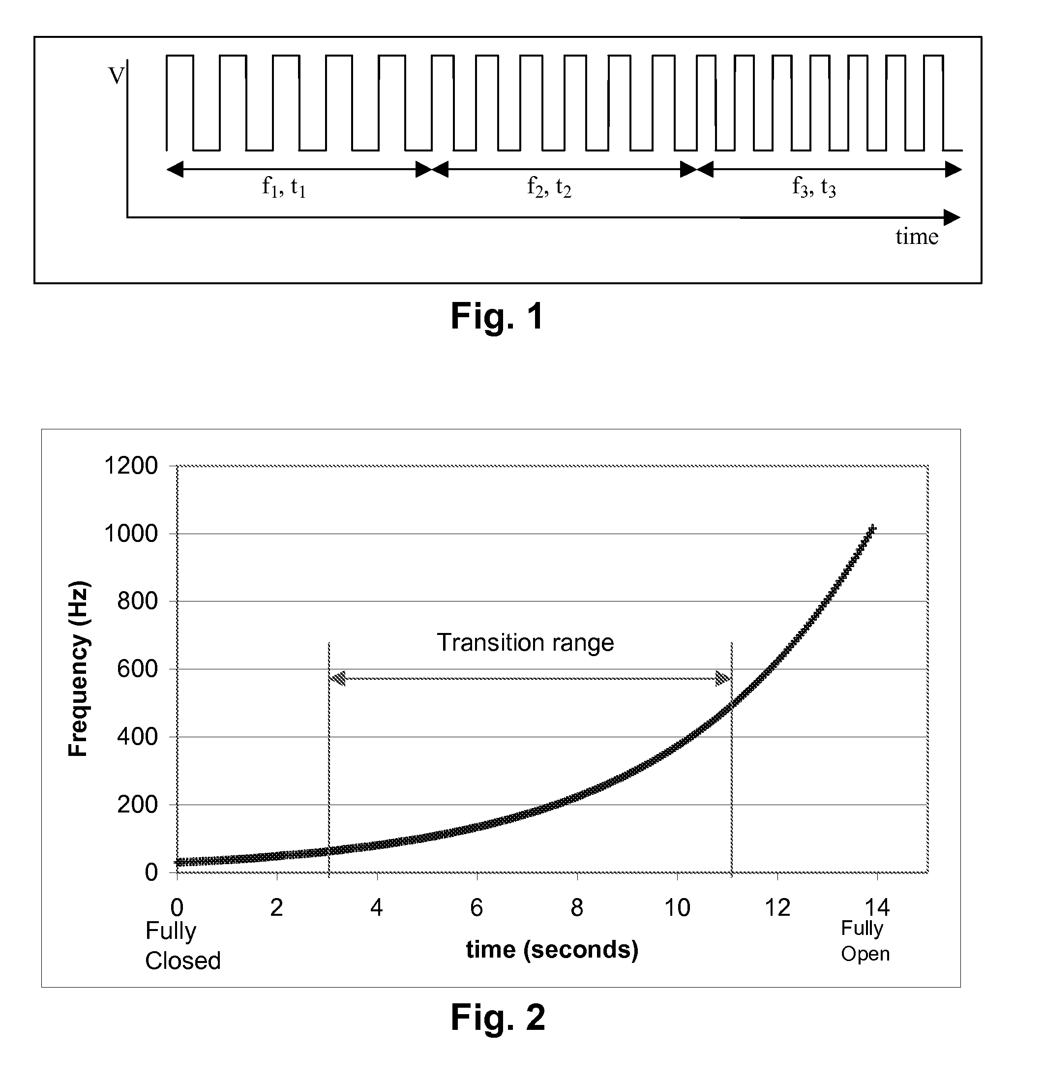
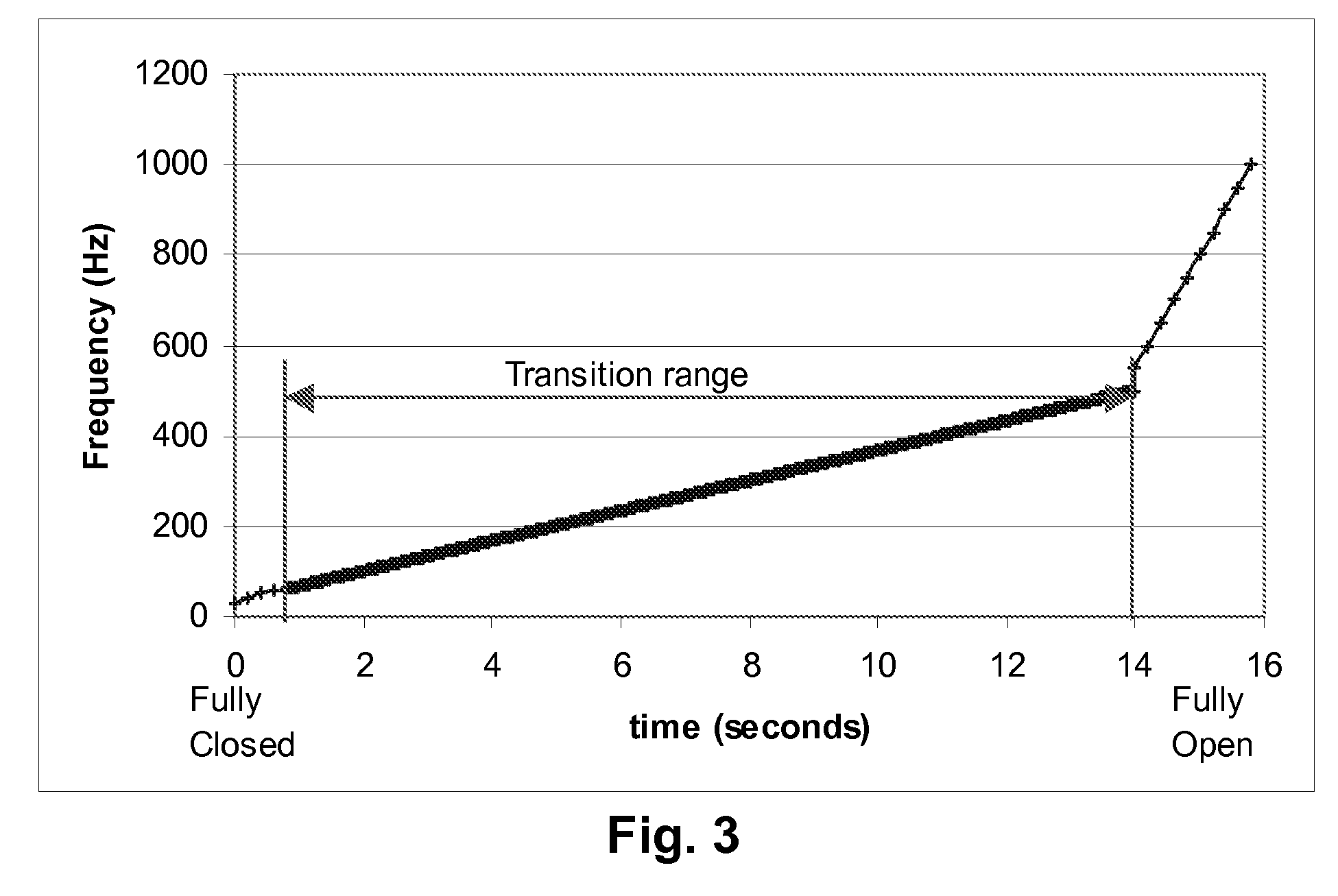
[0072]The frequency step method of the present invention is a method for operating a dielectrophoretic display which is a variation of the varying frequency drive method of the aforementioned 2006 / 0038772. In the method of the present invention, the display is driven using not only a low frequency which causes the particles to undergo electrophoretic motion and produce a first optical state, and a high frequency which causes the partic...


PUM


Abstract

A dielectrophoretic display is shifted from a low frequency closed state to a high frequency open state via at least one, and preferably several, intermediate frequency states; the use of such multiple frequency steps reduces flicker during the transition. A second type of dielectrophoretic display has a light-transmissive electrode through which the dielectrophoretic medium can be viewed and a conductor connected to the light-transmissive electrode at several points to reduce voltage variations within the light-transmissive electrode.

Description

REFERENCE TO RELATED APPLICATIONS[0001]This application claims benefit of copending Application Ser. No. 60 / 887,876, filed Feb. 2, 2007.[0002]This application is also a continuation-in-part of copending application Ser. No. 11 / 460,358, filed Jul. 27, 2006 (Publication No. 2006 / 0256425), which is itself a divisional of application Ser. No. 11 / 161,179, filed Jul. 26, 2005 (now U.S. Pat. No. 7,116,466), which itself claims benefit of Application Ser. No. 60 / 591,416, filed Jul. 27, 2004.[0003]This application is also a continuation-in-part of copending application Ser. No. 11 / 162,188, filed Aug. 31, 2005 (Publication No. 2006 / 0038772), which claims benefit of Application Ser. No. 60 / 605,761, filed Aug. 31, 2004[0004]This application is also related to:[0005](a) copending application Ser. No. 10 / 907,140, filed Mar. 22, 2005 (Publication No. 2005 / 0213191), which itself claims benefit of provisional Application Ser. No. 60 / 555,529, filed Mar. 23, 2004, and of provisional Application Ser. N...

Claims


Application Information

Patent Timeline
IPC IPC(8): G09G3/34G02B26/00G02F1/167G02F1/1676
CPCG02F1/1345G02F1/167G09G2320/0223G09G3/344G09G2310/06G02F2202/42G02F1/1676G02F1/13306G09G3/2007G09G2320/0247
Inventor HARRIS, GEORGE G.PAOLINI, RICHARD J.WHITESIDES, THOMAS H.MCCREARY, MICHAEL D.HONEYMAN, CHARLES HOWIE
Owner E INK CORPORATION
Why Eureka
Try Eureka