Integrally formed single piece light emitting diode light wire

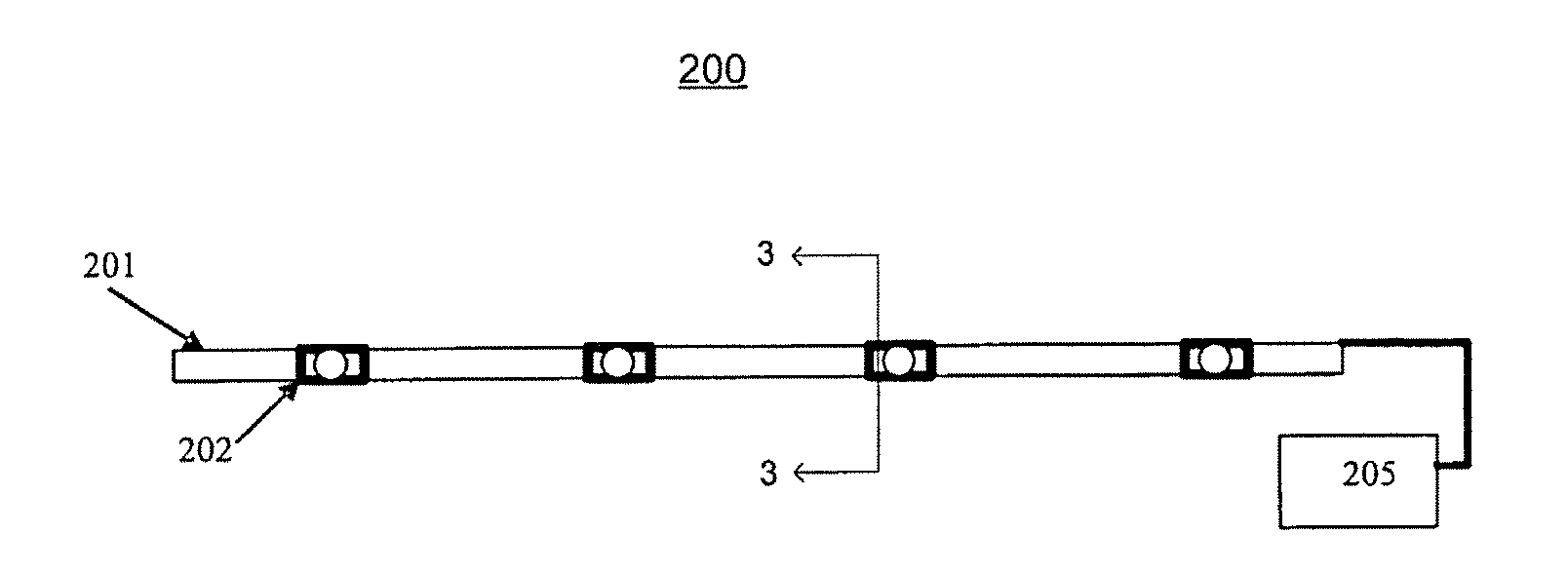
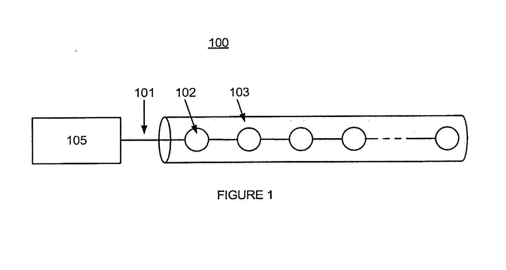
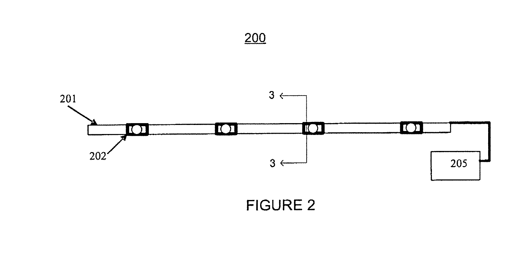
a light wire and light wire technology, applied in the field of integrated single-piece light wires, can solve the problems of unsuitable outdoor use of conventional light wires b>100/b> with protective tubes b>103/b>, unreliable manufacturing processes, and insufficient protection of internal circuitry from environmental hazards, so as to reduce the number of separate parts, reduce the number of procedures, parts, equipment, and improve the effect of ar

Active Publication Date: 2008-06-12
HUIZHOU LIGHT ENGINE LTD
View PDF26 Cites 71 Cited by
  • Summary
  • Abstract
  • Description
  • Claims
  • Application Information

AI Technical Summary

Benefits of technology

[0012]In light of the above, there exists a need to further improve the art. Specifically, there is a need for an improved integrally formed single piece LED light wire that is flexible and provides a smooth, uniform lighting effect from all directions of the integrally formed single piece LED light wire.

Problems solved by technology

Furthermore, the protective tube 103 does not sufficiently protect the internal circuitry from environmental hazards, such as water and dust.
As a result, these conventional light wires 100 with protective tube 103 are found unsuitable for outdoor use, especially when the light wires are exposed to extreme weather and/or mechanical abuse.
Such processes of manufacturing are labor intensive and unreliable.
Furthermore, such processes decrease the flexibility of the light wire.
In response to the above-mentione

Method used


Image

  • Integrally formed single piece light emitting diode light wire
  • Integrally formed single piece light emitting diode light wire
  • Integrally formed single piece light emitting diode light wire

Examples


first embodiment

of the Conductive Base

[0077]In a first embodiment of the conductive base assembly 600, shown in FIG. 6A, the base material of the conductive base 601 is preferably a long thin narrow metal strip or foil. In one embodiment, the base material is copper. A hole pattern 602, shown as the shaded region of FIG. 6A, depict areas where material from the conductive base 601 has been removed. In one embodiment, the material has been removed by a punching machine. The remaining material of the conductive base 601 forms the circuit of the present invention. Alternatively, the circuit may be printed on the conductive base 601 and then an etching process is used to remove the areas 602. The pilot holes 605 on the conductive base 600 act as a guide for manufacture and assembly.

[0078]The LEDs 202 are mounted either by surface mounting or LED chip bonding and soldered, welded, riveted or otherwise electrically connected to the conductive base 601 as shown in FIG. 6A. The mounting and soldering of th...

second embodiment

of the Conductive Base

[0079]To create series and / or parallel circuitries, additional material is removed from the conductive base. As shown in FIG. 7A, the conductive base 701 has an alternative hole pattern 702 relative to the hole pattern 602 depicted in FIG. 6A. With the alternative hole pattern 702, the LEDs 202 are connected in series on the conductive base 701. The series connection is shown in FIG. 7B, which is a schematic diagram of the conductive base assembly 700 shown in FIG. 7A. As shown, the mounting portions of LEDs 202 provide support for the conductive base 701.

third embodiment

of the Conductive Base

[0080]In a third embodiment of the conductive base, as shown in FIG. 8A, a conductive base assembly 800 is depicted having a pattern 802 is punched out or etched into the conductive base 801. Pattern 802 reduces the number of punched-out gaps required and increase the spacing between such gaps. Pilot holes 805 act as a guide for the manufacturing and assembly process. As shown in FIG. 8B, the LEDs 202 are short-circuited without the removal of additional material. In one embodiment, the material from conductive base 801 is removed after the LEDs 202 are mounted.


PUM


Abstract

A flexible, integrally formed single piece light emitting diode (LED) light wire that provides a smooth, uniform lighting effect from all directions of the LED light wire. The integrally formed single piece LED light wire contains a conductive base comprising first and second bus elements formed from a conductive material. The bus elements distribute power from a power source to LEDs that are mounted on the first and second bus elements so that it draws power from and adds mechanical stability to the first and second bus elements. The flexible, integrally formed single piece LED light wire is assembled so that the first and second bus elements are connected to each other prior to the LED being mounted and such integrally formed single piece LED light wire is formed without a substrate.

Description

CROSS-REFERENCE TO RELATED APPLICATIONS[0001]This is a utility application claiming priority under 35 U.S.C. § 119(e) to U.S. Provisional Patent Application Ser. No. 60 / 844,184, filed Sep. 12, 2006, the entirety of which is incorporated herein by reference.[0002]Throughout this application, several publications are referenced. Disclosure of these references in their entirety is hereby incorporated by reference into this application.[0003]The present invention relates to light wires and, more specifically, an integrally formed single piece of light wire containing light emitting diodes (“LEDs”), and systems and processes for manufacturing such a light wire, wherein the LEDs and associated circuitry are protected from mechanical damage and environmental hazards, such as water and dust.BACKGROUND THE INVENTION[0004]Conventional incandescent or LED light wires are commonly used in a variety of indoor and outdoor decorative or ornamental lighting applications. For example, such conventio...

Claims


Application Information

Patent Timeline
IPC IPC(8): F21S4/00F21V23/00H05B44/00
CPCF21S4/006F21Y2101/02F21Y2103/003Y10S362/80H05B33/04F21V31/04F21S2/005H05B33/0803H01L2224/48091H01L2224/48247F21S4/24F21Y2103/10F21Y2115/10H01L2924/00011H05B45/30H01L2924/00014H01L2924/01033
Inventor LO, PAULLO, TEDDY YEUNG MAN
Owner HUIZHOU LIGHT ENGINE LTD
Why Eureka
Try Eureka