
External Force Control Method, External Force Control System and External Force Control Program

a technology of external force and control system, applied in the direction of prosthesis, application, person identification, etc., can solve the problem that the myoelectric signal does not provide the desired force applied to the person by conventional technologies

Inactive Publication Date: 2008-06-12
HONDA MOTOR CO LTD
View PDF21 Cites 40 Cited by
  • Summary
  • Abstract
  • Description
  • Claims
  • Application Information

AI Technical Summary

Benefits of technology

[0009]Therefore, according to the external force control method of the present invention, it is possible to control the external force f on the basis of the myoelectric potential x in such a way that the relation between the external force f and the motion variable y approaches the target relation (γt=γ(f, y)), which is determined according to the factor target value γt, even if any change occurs in the myoelectric potential measurements of the animal.
[0032]According to the external force control program of the present invention, it is possible to provide the computer with the functions for controlling the external force f based on the myoelectric potential x in such a way that the relation between the external force f and the motion variable y approaches the target relation (γt=γ(f, y)) determined according to the factor target value γt, even if any change occurs in the myoelectric potential measurements of the animal.

Problems solved by technology

If there is any change in muscle fatigue degree or in the contact condition between electrodes and the body due to perspiration or the like, it is projected that the relation between the myoelectric signal and the joint torque changes even in the same person and that simply adopting the conventional technologies does not provide a desired force applied to the person based on the myoelectric signal.

Method used


Image

  • External Force Control Method, External Force Control System and External Force Control Program
  • External Force Control Method, External Force Control System and External Force Control Program
  • External Force Control Method, External Force Control System and External Force Control Program

Examples


Embodiment Construction

[0038]Preferred embodiments of an external force control method, an external force control system, and an external force control program according to the present invention will be described by using the accompanying drawings.

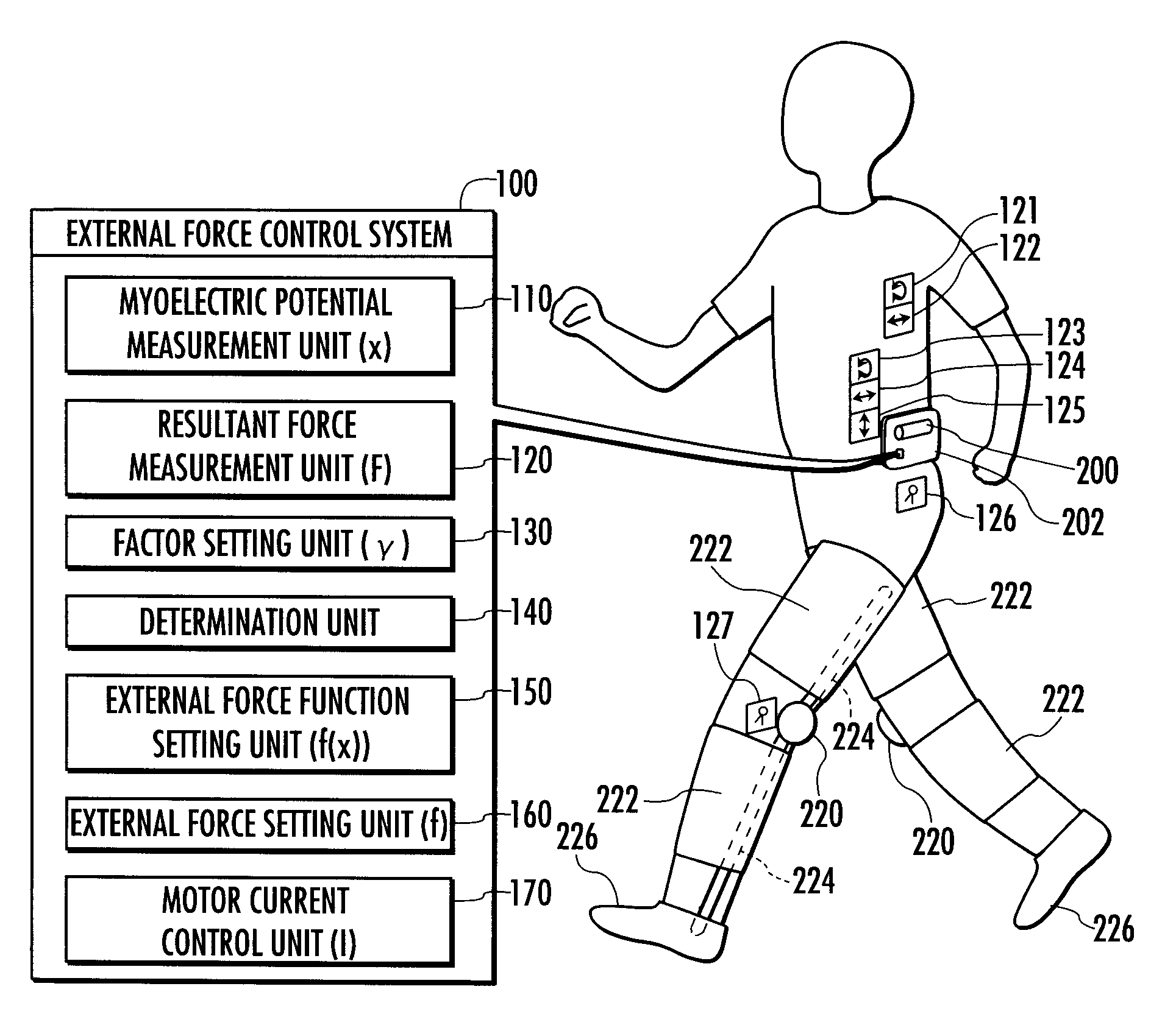
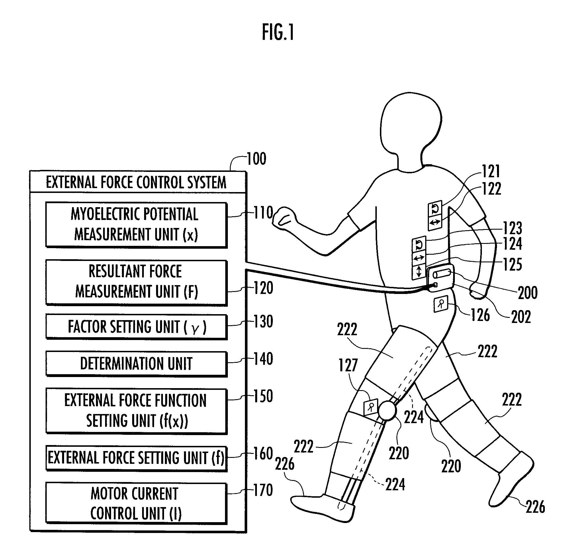
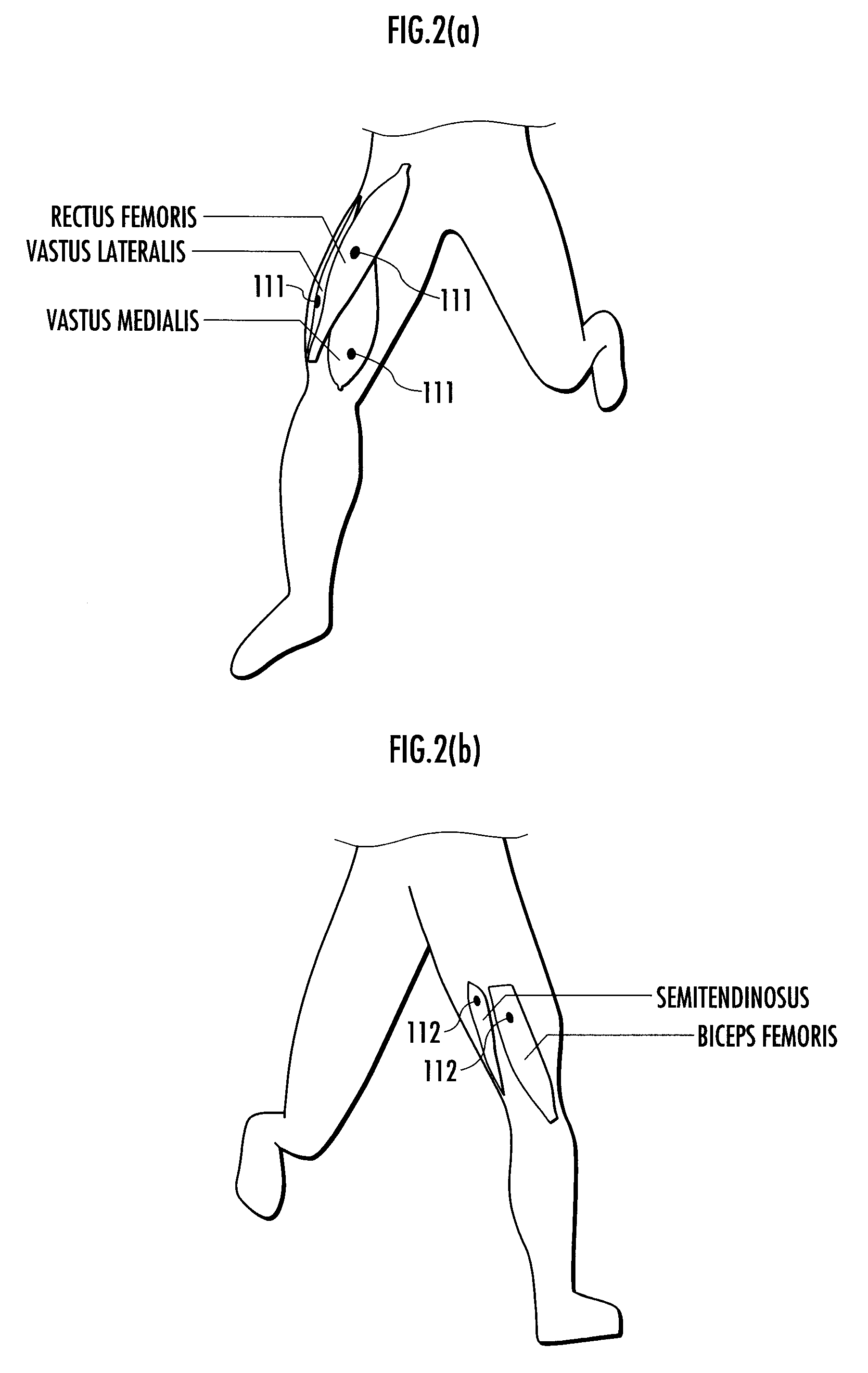
[0039]The following describes the configuration of the external force control system in one embodiment of the present invention with reference to FIG. 1 and FIG. 2.

[0040]An external force control system 100 shown in FIG. 1 controls external torques (external forces) around the knee joints of a person (animal) applied to both left and right legs through orthoses 222 attached to the thigh and crus of the legs by means of motors (engines) 220 disposed on the person's left and right knees, respectively. The motors 220 work with a battery 200 as a power supply, which is contained in a case 202 attached to the waist.

[0041]The external force control system 100 includes a myoelectric potential measurement unit 110, a resultant force measurement unit (motion variable mea...


PUM


Abstract

A method of controlling an external force applied to an animal to achieve as a target relation the relation between the external force and a motion variable varying with the motion of the animal.A value of an external force f applied to a human leg according to an external force function f(x) on the basis of a measured value of a myoelectric potential x that occurs in the human leg, current I of a motor 220 is controlled according to the set value, and the external force f is applied to the leg through an orthosis 222. A resultant force (the sum of an internal torque and an external torque around a knee joint) F is measured as “a motion variable.” Moreover, a value of a factor γ is set according to a factor function γ(f, F) on the basis of the set value of the external force f and the measured value of the resultant force F. If a deviation δ between the set value of the factor γ and target value γt thereof is equal to or greater than a reference value ε, a new external force function f(x) is set in such a way that the set value of the factor γ approaches the target value γt.

Description

TECHNICAL FIELD [0001]The present invention relates to a method and system for controlling an external force applied to an animal through an orthosis attached to the animal that makes a movement along with the activities of muscle fibers and a program for providing a computer with the control functions.BACKGROUND ART [0002]An external force applied to a person with the purpose of walking aid is preferably controlled to an appropriate one in relation to an internal force that arises due to his or her will according to the progress of rehabilitation exercise or the like. Therefore, it is conceivable to measure a joint torque on the basis of a myoelectric signal that occurs in a human body and to apply a torque (external force) of an appropriate level according to the joint torque to the person.[0003]Conventionally, there has been suggested a technology of estimating a muscle force of a leg by an output from a pressure sensor or the like attached to the toe or heel of a sole and applyi...

Claims


Application Information

Patent Timeline
Patent Type & Authority Applications(United States)
IPC IPC(8): A61B5/103A61B10/00
CPCA61B5/04888A61H3/00A61H1/0237A61B5/4528A61F2/72
Inventor ENDO, YOSUKEHARA, RITSUO
Owner HONDA MOTOR CO LTD
Learn More