Robot control apparatus for force control

a robot control and force technology, applied in the field of robot control apparatus, can solve the problems of inability to perfect estimate, insufficient or excessive machined workpieces, incomplete control of pushing force by robots,

Inactive Publication Date: 2008-06-12
FANUC LTD
View PDF14 Cites 97 Cited by
  • Summary
  • Abstract
  • Description
  • Claims
  • Application Information

AI Technical Summary

Benefits of technology

[0023]Specifically, according to the fifth aspect, the target trajectory is changed in accordance with inertia force obtained from the dynamic terms and the operating direction, thereby making it possible to machine the workpiece in the desired state.

Problems solved by technology

Further, in the case where the direction in which the forward end portion of the robot arm moves is changed a comparatively great degree in a trace machining operation, the pushing force by the robot may be controlled incompletely and the workpiece may be machined insufficiently or excessively.
However, since these values always contain an error, a perfect estimate is impossible.
In the case where the direction in which the forward end portion of the robot arm is changed to a comparatively great degree, the dynamic terms are also increased, and therefore, the error also tends to increase.
Also, the delay of the control system and the limitation of the trackability may cause a situation in which the workpiece cannot be machined as desired by the mere compensation of the dynamic terms.

Method used


Image

  • Robot control apparatus for force control
  • Robot control apparatus for force control
  • Robot control apparatus for force control

Examples


Embodiment Construction

[0045]An embodiment of the invention will be explained below with reference to the accompanying drawings. In the drawings, similar component members are designated by the same reference numerals, respectively. To facilitate understanding, the scale of the drawings has been appropriately changed.

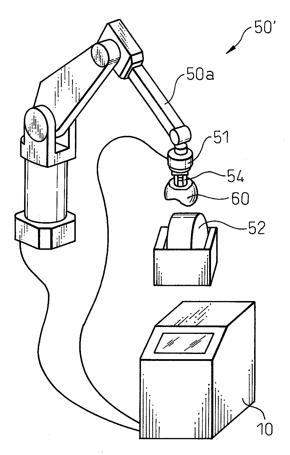
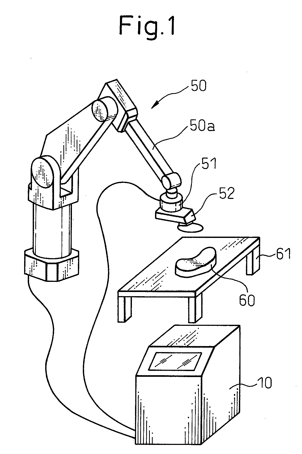
[0046]FIG. 1 is a perspective view of the robot controlled by the robot control apparatus according to this invention. The robot 50 shown in FIG. 1 is a multijoint robot equipped with 6 degrees of freedom. Robot 50 is controlled by the robot control apparatus 10. A working tool 52 is mounted at the forward end of the robot arm 50a of the robot 50. According to the embodiment shown in FIG. 1, the working tool 52 is a grinder, for example. The working tool 52 such as the grinder shown in FIG. 1 is used for grinding the workpiece 60 fixed on a work bench 61.

[0047]Further, a force sensor 51 is arranged between the forward end of the robot arm 50a and the working tool 52. The force sensor 51 measu...


PUM


Abstract

A robot control apparatus for controlling force exerted between a working tool mounted at the forward end of a robot arm and a workpiece is disclosed. The apparatus includes a force measuring unit for acquiring the force data required for the control operation, a calculating unit for calculating the force exerted by gravity on the force measuring unit and the dynamic terms generated by the motion of the robot arm, of all the forces exerted on the force measuring unit from the working tool, a compensation unit for compensating the force measured by the force measuring unit using the force exerted by gravity and the dynamic terms calculated by the calculating unit, and a command adjusting unit for adjusting the operation command for the robot arm in accordance with the force exerted on the force measuring unit by the dynamic terms and gravity in the case where each of the dynamic terms is larger than a predetermined threshold value. As a result, the workpiece can be accurately machined even in the case where the forward end portion of the robot arm is changed a comparatively great degree in the direction of movement thereof.

Description

BACKGROUND OF THE INVENTION[0001]1. Field of the Invention[0002]This invention relates to a robot control apparatus, or in particular, to a robot control apparatus for controlling machining such as deburring, grinding and polishing using a robot.[0003]2. Description of the Related Art[0004]In order to carry out machining such as deburring, polishing or grinding using a robot, a working tool mounted at the forward end of a robot arm is moved while being pushed against a workpiece with an appropriate amount of force. For a similar purpose, a workpiece held in the hand mounted at the forward end of the robot arm may be pushed against a machine tool fixed with an appropriate amount of force while at the same time moving the hand.[0005]In the process, a working tool or a machine tool having the compliance control mechanism may be used to make sure that a proper amount of force is exerted between the workpiece and the working tool. Also, the force exerted between the workpiece and the wor...

Claims


Application Information

Patent Timeline
Patent Type & Authority Applications(United States)
IPC IPC(8): B25J13/08B25J19/02
CPCB25J9/1633B25J9/1638G05B2219/39178G05B2219/39343G05B2219/39319G05B2219/39341G05B2219/39194
Inventor SATO, TAKASHIIWATAKE, TAKAHIRO
Owner FANUC LTD
Why Eureka
Try Eureka