Systems and methods for shock compensation utilizing an adaptive control technique algorithm

a technology of adaptive control and algorithm, applied in the field of flight control systems, can solve the problems of destroying the imu, affecting the performance of certain components of the flight control system, and the above described inertial measurement units (imus), and achieve the effect of attenuating the effects of the dynamic disturban

Inactive Publication Date: 2008-06-12
HONEYWELL INT INC
View PDF5 Cites 21 Cited by
  • Summary
  • Abstract
  • Description
  • Claims
  • Application Information

AI Technical Summary

Problems solved by technology

Certain components of flight control systems, for example, the above described inertial measurement units (IMUs), are likely to experience performance degradation when exposed to motion as a result of body bending and induced vibration.
These shock wave transients, when above predefined and specified thresholds, may be destructive to the IMU.

Method used


Image

  • Systems and methods for shock compensation utilizing an adaptive control technique algorithm
  • Systems and methods for shock compensation utilizing an adaptive control technique algorithm
  • Systems and methods for shock compensation utilizing an adaptive control technique algorithm

Examples


Embodiment Construction

[0009]At least some known inertial measurement units, sometimes referred to as IMU packages, are not currently capable of surviving shocks and vibrations that result from accelerations exceeding certain acceleration (G) levels. The systems and methods described herein provide in-system dynamic compensation to known IMU packages and reduce the sensitivity of such IMU packages to high shock and vibration levels. The systems and methods are also applicable to other systems that require control and attenuation of high shock and vibration levels.

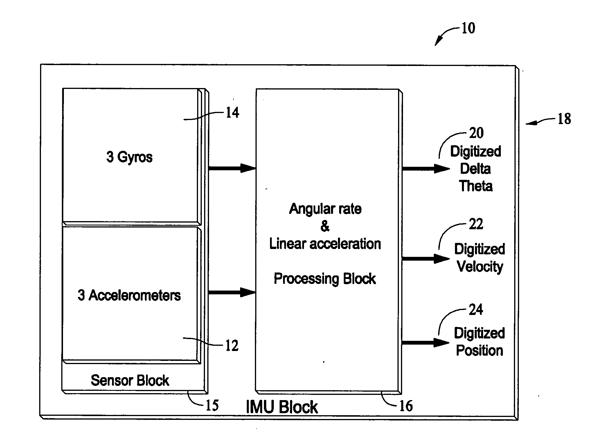
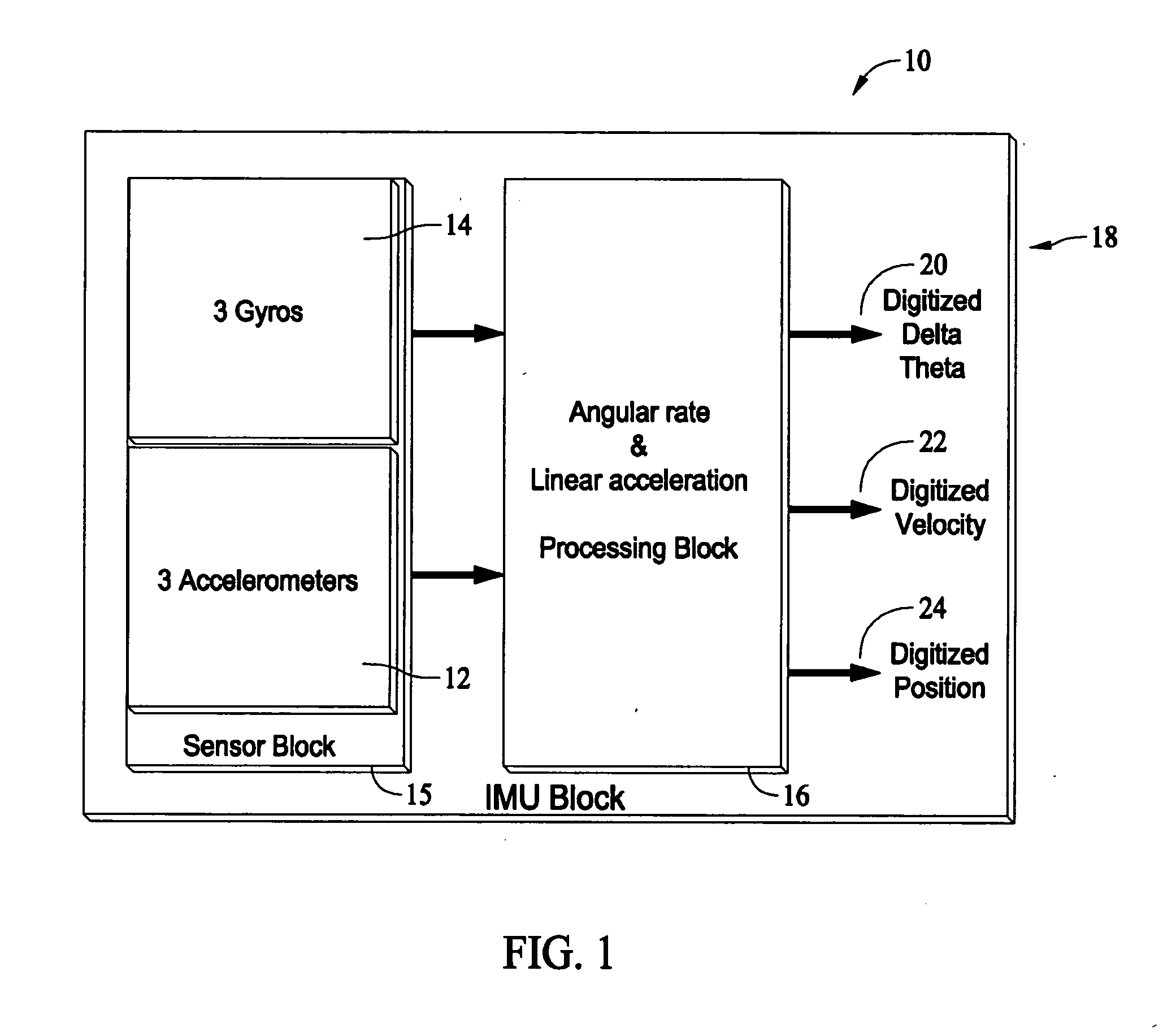
[0010]FIG. 1 is a block diagram of an inertial measurement unit (IMU) 10. IMU 10 includes accelerometers 12 and gyroscopes 14 in a sensor block 15 providing inertial data to a processing block 16 which includes at least one analog to digital converter (not shown). In a typical embodiment, accelerometers 12 includes three orthogonal accelerometers and gyroscopes 14 includes three orthogonal gyroscopes.

[0011]Various types of accelerometers and gyro...


PUM


Abstract

A method for providing dynamic disturbance compensation to an inertial system is described. The method includes determining estimated correction factors based on received acceleration components, and dynamically determining filter coefficients for a filter configured to receive velocity and position signals and output a prediction error. The method further includes combining the estimated correction factors and the prediction error into adjustment factors, where the prediction error is configured to be a feedback control signal, and applying the adjustment factors to compensate the inertial system such that effects of the dynamic disturbance are removed.

Description

BACKGROUND OF THE INVENTION[0001]This invention relates generally to flight control systems, and more specifically, to methods and systems for providing dynamic disturbance compensation for a flight platform, for example, shock compensation during a flight utilizing adaptive control techniques.[0002]An inertial sensor assembly (ISA), typically includes an inertial measurement unit (IMU) that detects acceleration and rotation in three planes. A typical IMU includes three accelerometers and three rotational rate sensors arranged with their input axes in a perpendicular relationship. The accelerometers and sensors are generally rigidly and precisely mounted within a housing along with other related electronics and hardware. Commonly, the housing is mounted to a support or chassis through suspension mounts or vibration isolators. The chassis is rigidly and precisely mounted to a frame of a vehicle, such as an aircraft or missile. An ISA typically forms a portion of a flight control syst...

Claims


Application Information

Patent Timeline
Patent Type & Authority Applications(United States)
IPC IPC(8): G01C21/00G01S19/21G01S19/26
CPCG01C25/005G01C21/16G01C21/185G01C21/188
Inventor MASSON, SIMEON
Owner HONEYWELL INT INC
Why Eureka
Try Eureka