
Method and a control system for monitoring the condition of an industrial robot

a technology of industrial robots and control systems, applied in the direction of instruments, nuclear elements, force/torque/work measurement apparatus, etc., can solve the problems of increasing friction, playing between, and reducing friction value, so as to achieve strong reduction of robot performance or damage

Inactive Publication Date: 2008-06-12
ABB RES LTD
View PDF10 Cites 28 Cited by
  • Summary
  • Abstract
  • Description
  • Claims
  • Application Information

AI Technical Summary

Benefits of technology

"The invention provides a method for monitoring malfunctions of industrial robots by calculating the mechanical properties of joints and monitoring changes in these properties over time. This allows for early detection of malfunctions and timely maintenance or replacement of the robot. The method can be used in conjunction with existing sensors and data collection systems, and can provide a more accurate indication of malfunctions than simply monitoring changes in motor torque or angular position. The calculated mechanical properties and condition parameters can be used to determine the root cause of the malfunction and take appropriate action, such as initiating service of the robot or replacing a malfunctioning part. The method can also be used for automated supervison and can detect the degree of malfunction based on the deviation of the calculated mechanical property value from its expected value."

Problems solved by technology

An increase in friction, for example, depends on wear of the bearings of the robot or bad oil.
An increase in play may depend on wear of the bearing that results in a play between the teeth of the bearing.
This type of wear of the bearing may lead to a decrease of the friction value.

Method used


Image

  • Method and a control system for monitoring the condition of an industrial robot
  • Method and a control system for monitoring the condition of an industrial robot
  • Method and a control system for monitoring the condition of an industrial robot

Examples


first embodiment

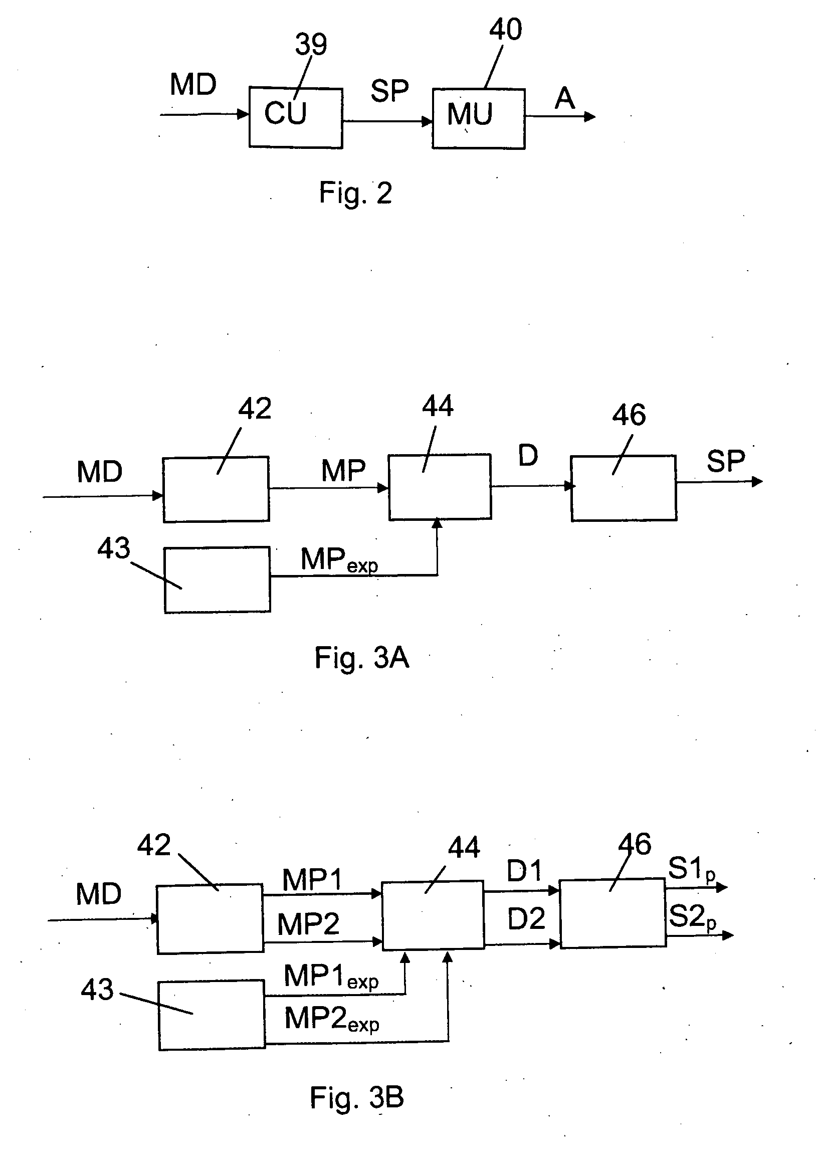
[0060]FIG. 3A shows the method for monitoring malfunction of an industrial robot and is also describing an embodiment of the calculating unit 39 more in detail. The mechanical property value MP is calculated for the selected joint based on the measured data MD from the joint in a mechanical property calculating unit 42. An expected mechanical property MPexp is retrieved, for instance, from the memory of the control unit or calculated based on prestored data in a retrieving unit 43. Then the calculated mechanical property MP is compared with the expected mechanical property MPexp in a comparing unit 44, wherein a deviation D between the calculated mechanical property MP and the expected mechanical property MPexp is calculated. After that a condition parameter SP is calculated based on said deviation D in a condition calculating unit 46. The condition parameter is, for example, calculated as a quotient between the deviation and the expected mechanical property: SP=D / MPexp. If the diff...

second embodiment

[0063]FIG. 3B shows the invention and is also describing another embodiment of the calculating unit 39 more in detail. A first mechanical property value MP1 is calculated as described above. This embodiment of the method further comprises calculating a second value for a second mechanical property MP2.

[0064]The mechanical property values MP1 and MP2 are calculated in the mechanical property calculating unit 42. A first expected mechanical property MP1exp and a second expected mechanical property MP2exp are retrieved for each mechanical property from the retrieving unit 43. Then the calculated mechanical property values MP1 and MP2 are compared with the respective expected mechanical property MP1exp and MP2exp in the comparing unit 44. A first deviation D1 between the first calculated mechanical property MP1 and the expected first mechanical property MP1exp is calculated. A second deviation D2 between the second calculated mechanical property MP2 and the expected second mechanical pr...


PUM

PropertyMeasurementUnit
currentaaaaaaaaaa
mechanical propertyaaaaaaaaaa
torqueaaaaaaaaaa

Abstract

A method for monitoring the condition of an industrial robot having a plurality of links movable relative to each other about a plurality of joints. A first value for a first mechanical property for at least one of said joints is calculated based on measured data from the joint. Whether the mechanical property is normal or non-normal is determined based on the calculated mechanical property. The condition of the robot is monitored based on the calculated first value and determination. The first value, determination and monitoring are repeatedly carried out.

Description

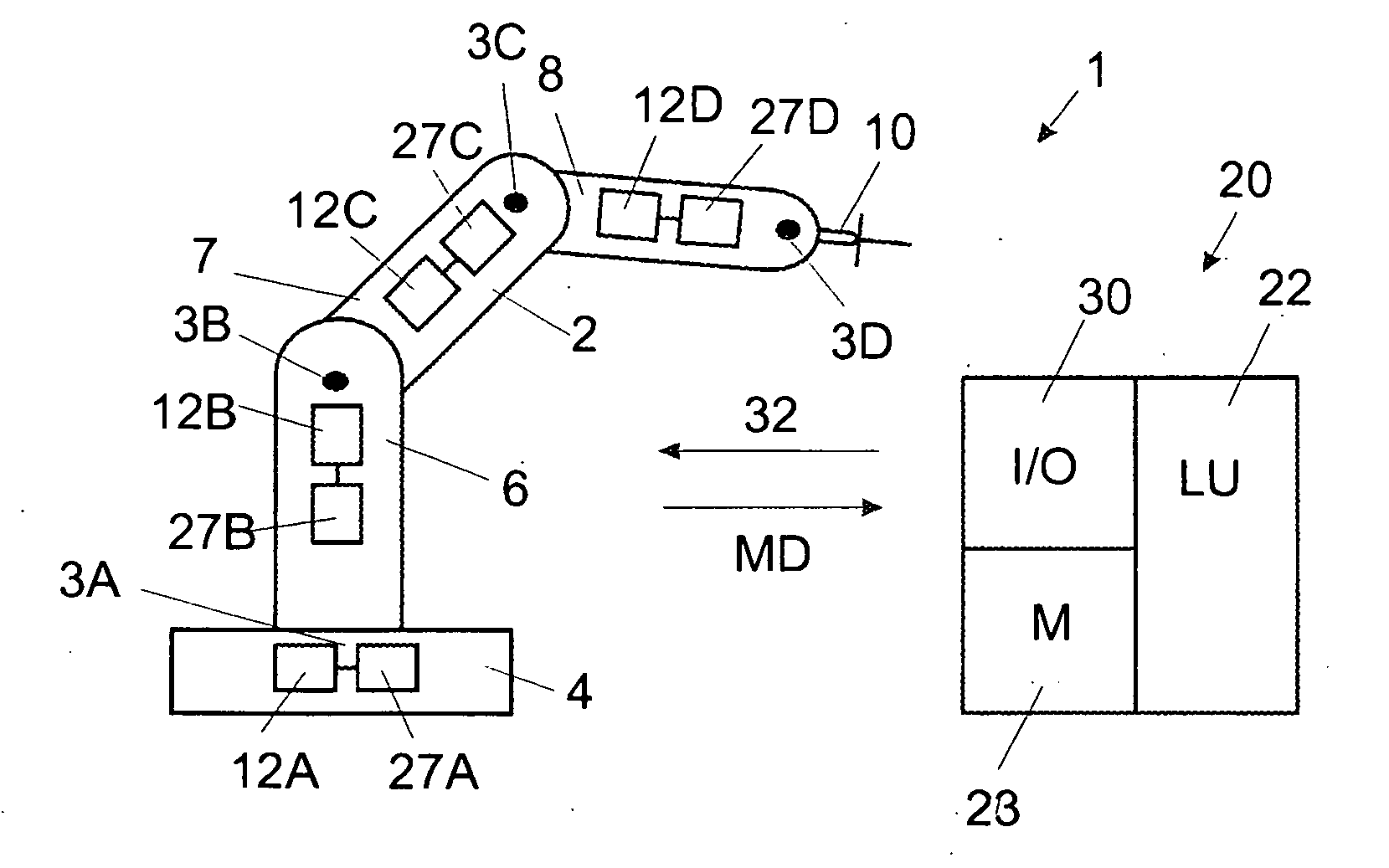
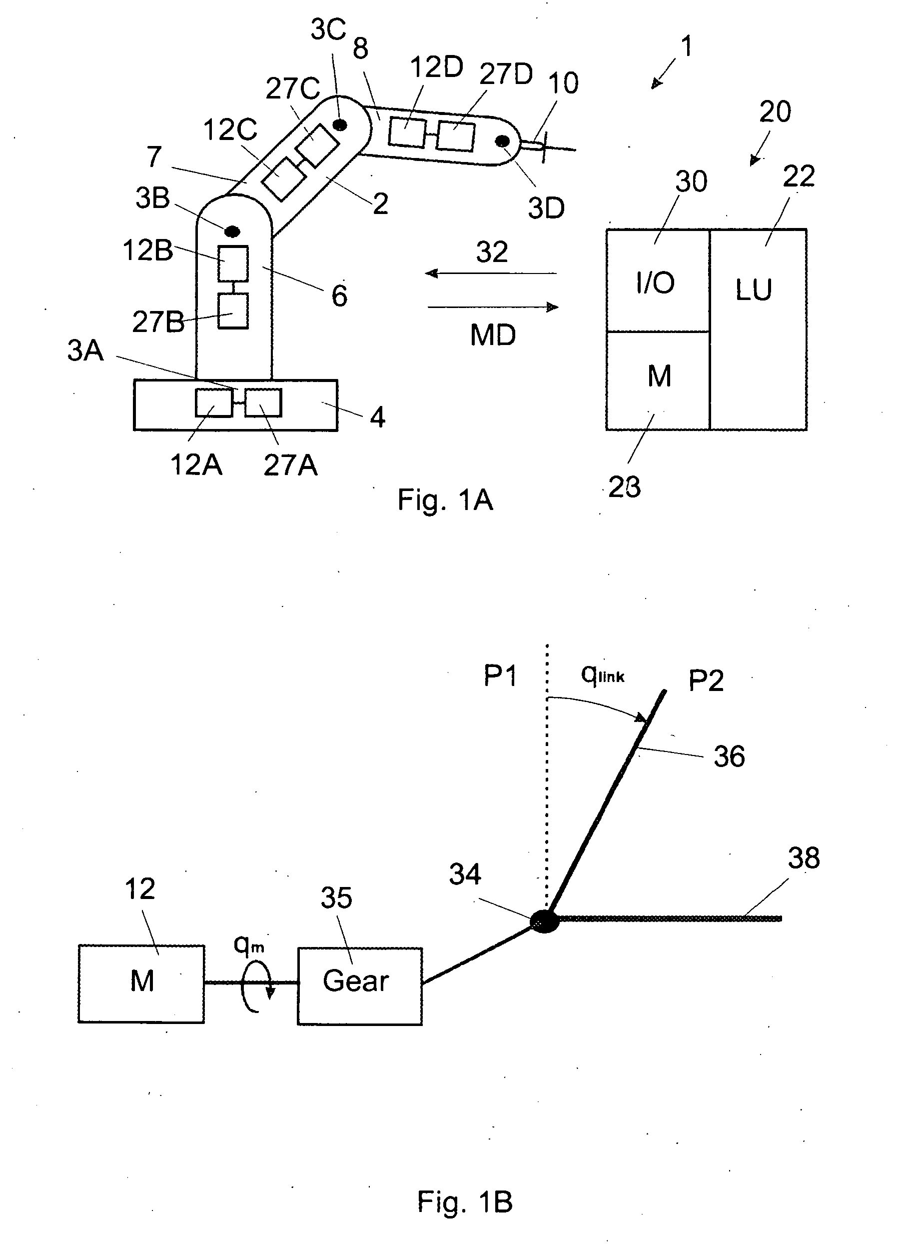
TECHNICAL FIELD[0001]The present invention is concerned with monitoring the performance of an industrial robot. The invention is particularly useful for detecting a malfunction of the robot.BACKGROUND ART[0002]An industrial robot comprises a manipulator and a control system. The manipulator comprises links movable relative to each other about a plurality of joints. The links are different robot parts such as a base, arms, and wrist. Each joint has joint components such as a motor, motor gear and motor bearings. The movements of the manipulator are driven by the motors. The control system comprises one or more computers and drive units for controlling the manipulator. The speeds and accelerations of the links are controlled by the control system of the robot that generates control signals to the motors.[0003]Industrial robots are used in industrial and commercial applications to perform precise and repetitive movements. It is then important for a faultless functionality of the robot ...

Claims


Application Information

Patent Timeline
Patent Type & Authority Applications(United States)
IPC IPC(8): G01L3/00G06F15/00
CPCB25J9/1674
Inventor BLANC, DOMINIQUESJOSTRAND, NICLAS
Owner ABB RES LTD
Learn More