

Method for performing oilfield production operations
- Summary
- Abstract
- Description
- Claims
- Application Information
AI Technical Summary
Benefits of technology
Problems solved by technology
Method used
Image

Examples
Embodiment Construction
[0061]Presently preferred embodiments of the invention are shown in the above-identified figures and described in detail below. In describing the preferred embodiments, like or identical reference numerals are used to identify common or similar elements. The figures are not necessarily to scale and certain features and certain views of the figures may be shown exaggerated in scale or in schematic in the interest of clarity and conciseness. Further, as used herein, the use of the term “lift gas” should include any possible resource that could provide lift and not be limited to merely include the use of gas.
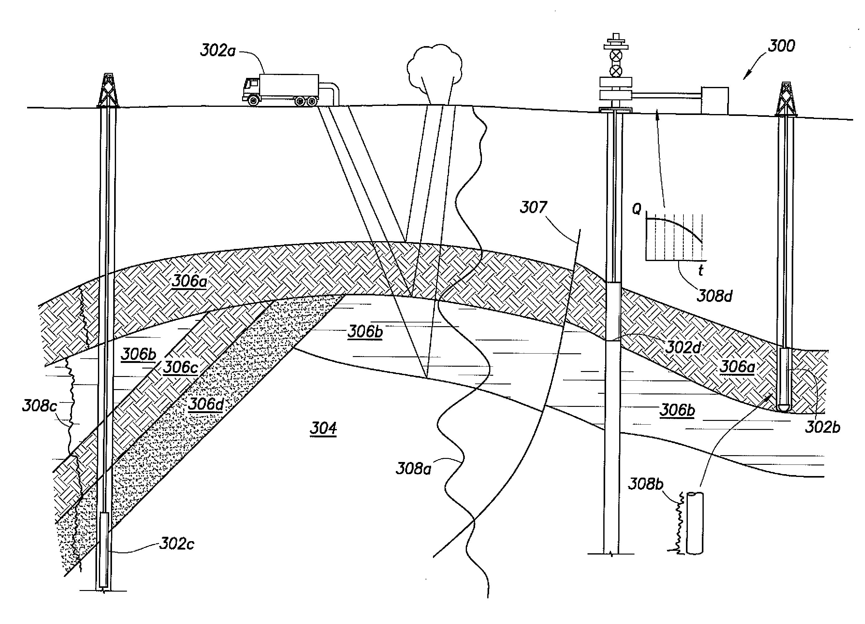
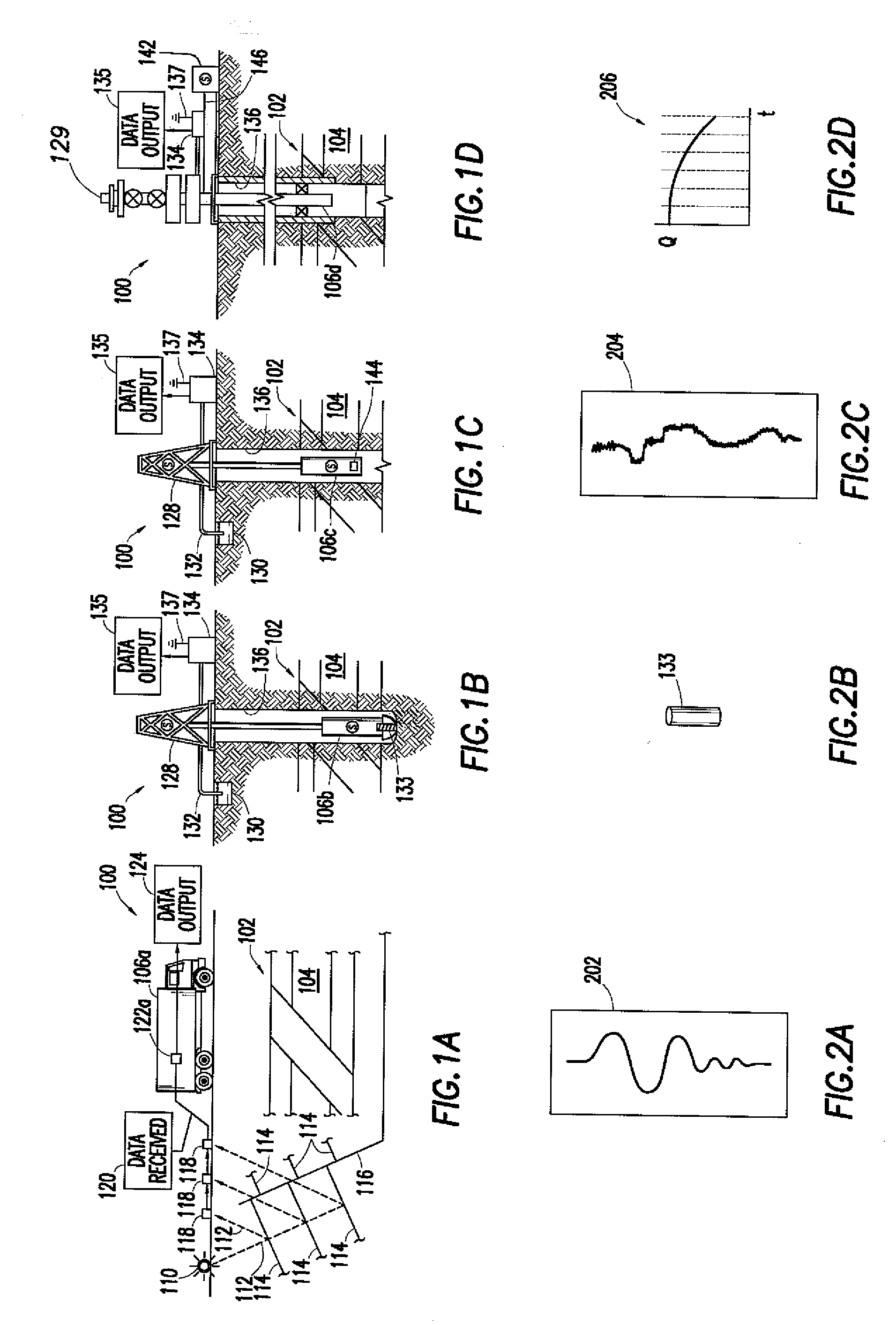
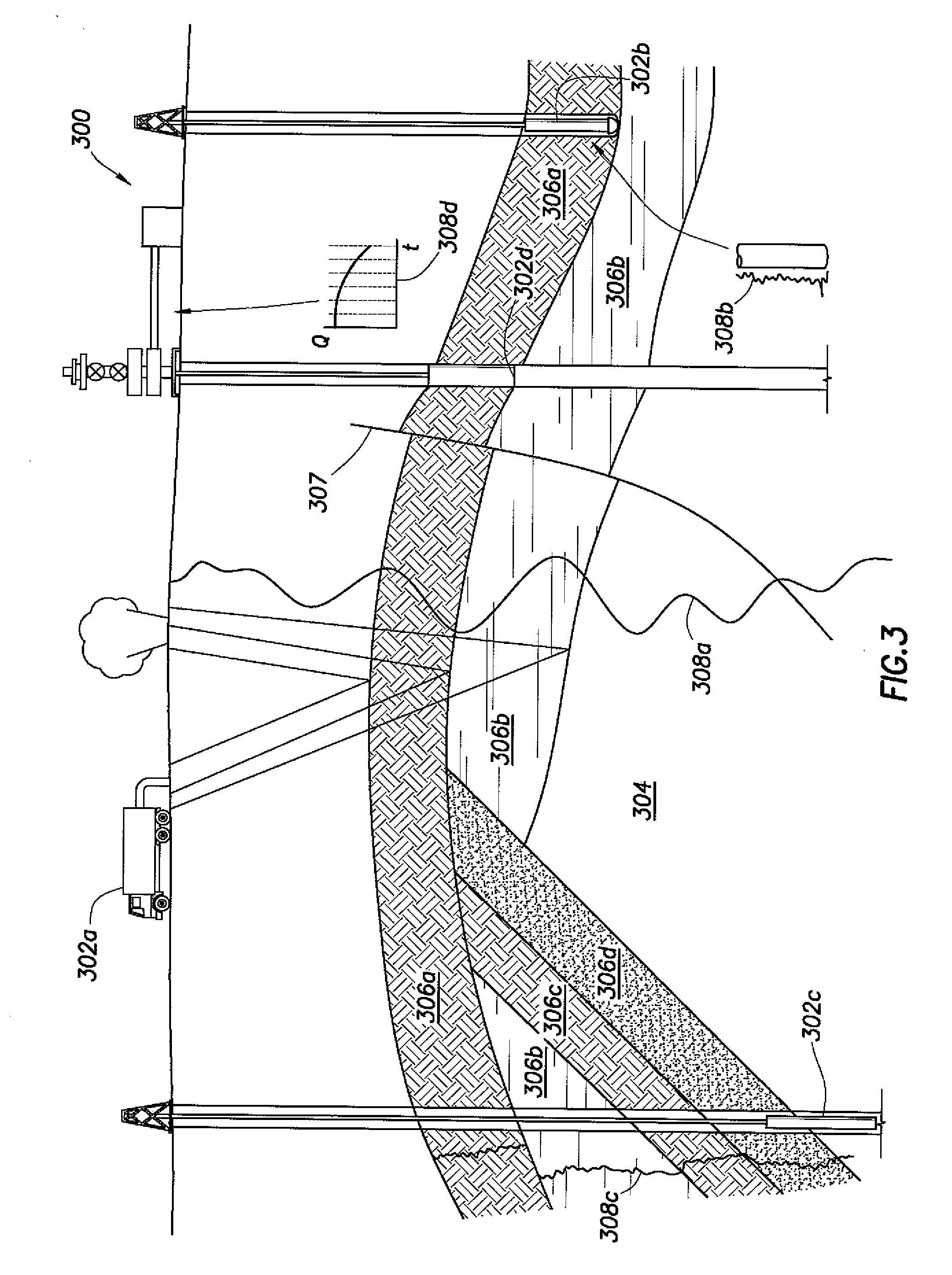
[0062]FIGS. 1A-1D depict simplified, representative, schematic views of an oilfield (100) having subterranean formation (102) containing reservoir (104) therein and depicting various oilfield operations being performed on the oilfield (100). FIG. 1A depicts a survey operation being performed by a survey tool, such as seismic truck (106a) to measure properties of the subterranean fo...
PUM
 Abstract
Description
Claims
Application Information