This helps you quickly interpret patents by identifying the three key elements:
Problems solved by technology
Method used
Benefits of technology
Benefits of technology
[0092]According to the present invention, since a limited blind signature that is received by the signature receiving apparatus is proven to be safe, without depending on a random oracle model, the possibility that an unauthorized receiving apparatus will obtain a signature without the assistance of the signature apparatus is very low. If there is exist an unauthorized receiving apparatus that can obtain a signature without the permission of the signature apparatus, then the strong RSA problem or the discrete logarithm problem or the like can be solved by using the receiving apparatus. The safety of many present public key encryption systems depends on these problems. The impact deriving from the existence of the above described unauthorized receiving apparatus would be to make most current public key encryption systems useless, and it is rare for such an incident to happen.
Problems solved by technology
However, if the electronic cash is used twice, since there is a limitation in which the electronic cash and I are associated with each other, I can be identified when I uses the electronic cash twice.
Method used
Image
Click on the blue label to locate the original text in one second.
Reading with bidirectional positioning of images and text.
Examples
embodiment 1
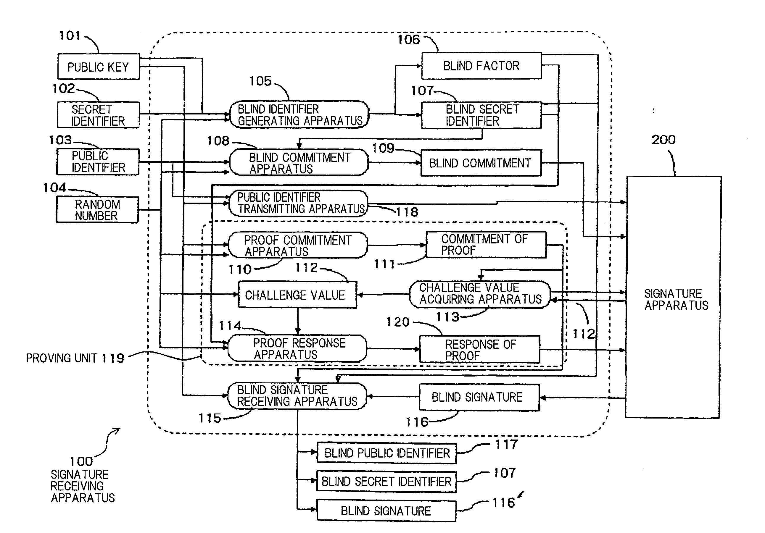
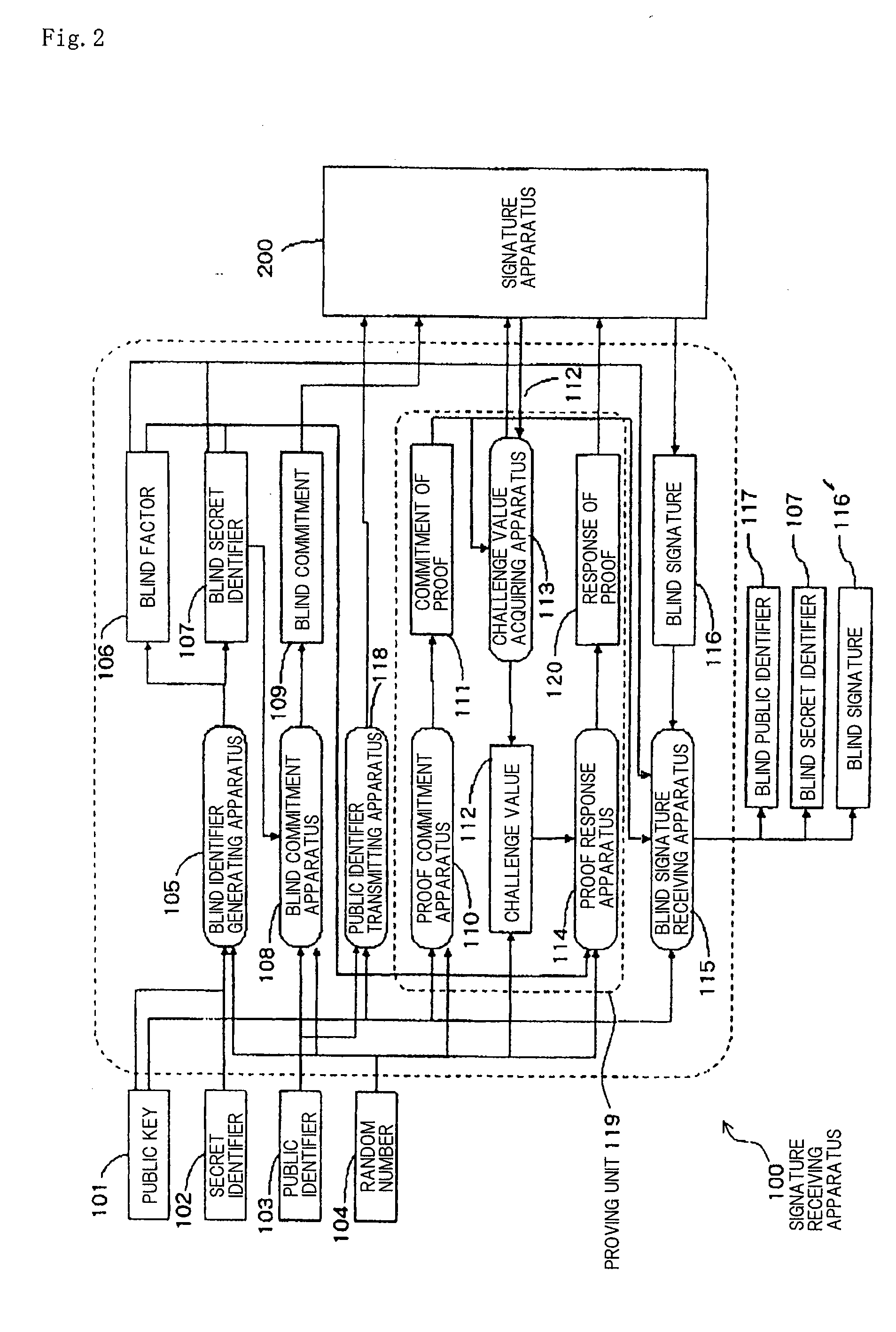
[0160]FIG. 2 is a block diagram showing an arrangement of signature receiving apparatus 100 according to a first embodiment of the present invention.
[0161]Signature receiving apparatus 100 sends data to and receives data from signature apparatus 200, is supplied with public key 101, secret identifier 102, public identifier 103, and random number 104, and outputs blind public identifier 117, blind secret identifier 107, and blind signature 116′. Signature receiving apparatus 100 comprises blind identifier generating apparatus 105, blind factor 106, blind secret identifier 107, blind commitment apparatus 108, blind commitment 109, proof commitment apparatus 110, commitment of proof 111, challenge value 112, challenge value acquiring apparatus 113, proof response apparatus 114, blind signature receiving apparatus 115, blind signature 116, public identifier transmitting apparatus 118, and response of proof 120.
[0162]Signature receiving apparatus 100 is implemented by a general computer ...
embodiment 2
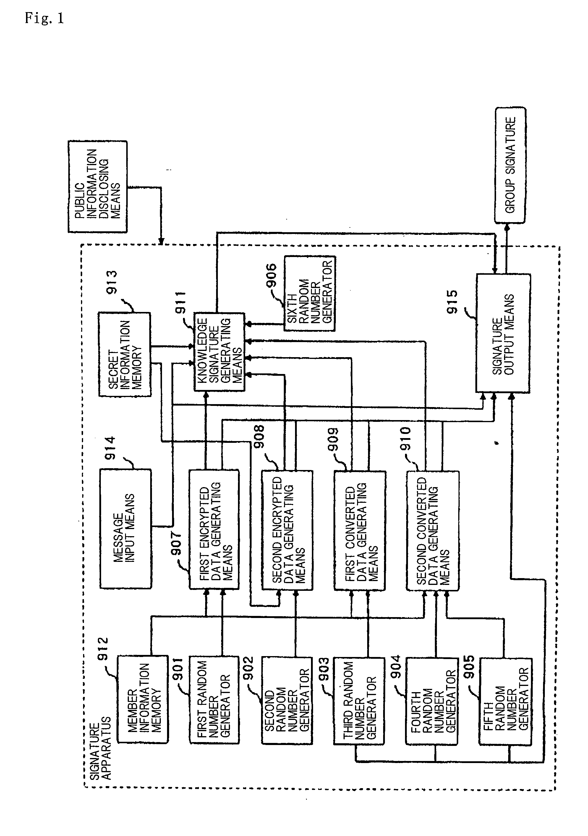
[0177]FIG. 3 is a block diagram showing an arrangement of signature apparatus 200 according to a second embodiment of the present invention.
[0178]Signature apparatus 200 is supplied with public key 101, secret key 201, and random number 202, and sends data to and receives data from signature receiving apparatus 100. Signature apparatus 200 comprises challenge value 112, blind signature 116, challenge value generating apparatus 203, proof verifying apparatus 205, verified result 206, group signature generating apparatus 207, public identifier receiving apparatus 208, and blind commitment receiving apparatus 209.
[0179]Signature apparatus 200 is implemented by a general computer system comprising an input device, an output device, a memory device, and a control device. Challenge value 112, blind signature 116, and verified result 206 are set in the memory device. Other devices are virtually established in the computer system. Of the above components, challenge value 112, challenge valu...
embodiments 3 , 4
EMBODIMENTS 3, 4
[0193]A process of proving to a signature verifying apparatus that a signature presenting apparatus holds a blind signature based on communications between the signature presenting apparatus and the signature verifying apparatus will be described below.
PUM
Abstract
The present invention is aimed at the proposal of a limited blind signaturesystem which is highly safe such that its safety can be proven without the assumption of a random oracle model. A signature presenting apparatus is supplied with a public key, a blind secret identifier, a blind public identifier, a blind signature, and a random number. A signature verifying apparatus outputs “valid” if the signature presenting apparatus is supplied with the data and otherwise outputs “invalid”.
Description
TECHNICAL FIELD[0001]The present invention relates to a blind signature method and apparatus for allowing a signature recipient to receive a signature to a message without the signer knowing the message that is determined by the signature recipient, and more particularly to a limited blind signature system and apparatus for limiting a signature that can be received by a signature recipient to a message related to a public identifier of the signature recipient.BACKGROUND ARTRelated Art 1[0002]One related example of a limited blind signature is a process described in Non-patent Document 1 (“Untraceable Off-line Cash in Wallets with Observers (Extended Abstract)” Advances in Cryptology, Proceedings Crypto '93, Lecture Note on Computer Science 773, D. Stinson, Ed., Springer-Verlag, 1994 pp. 302-318).[0003]The above process will briefly be described below. A limited blind signature employs three apparatus, i.e., a signature apparatus used by a signer, a signature receiving apparatus used...
Claims
Application Information
Patent Timeline
Application Date:The date an application was filed.
Publication Date:The date a patent or application was officially published.
First Publication Date:The earliest publication date of a patent with the same application number.
Issue Date:Publication date of the patent grant document.
PCT Entry Date:The Entry date of PCT National Phase.
Estimated Expiry Date:The statutory expiry date of a patent right according to the Patent Law, and it is the longest term of protection that the patent right can achieve without the termination of the patent right due to other reasons(Term extension factor has been taken into account ).
Invalid Date:Actual expiry date is based on effective date or publication date of legal transaction data of invalid patent.
Patent Type & AuthorityApplications(United States)

